Abstract A run-out error is the surface variation that occurs relative to a rotation axis. There are two types of run-out controls: circular run-out (2D) and total run-out (3D). Run-out tolerances are composite controls that define the requirements for the permissible coaxiality, orientation and form deviations of a surface element in relation to a datum axis. The application of the run-out control to an assembly and its combination with the tangent plane symbol, are illustrated in this chapter as main novelties of the new ASME Y14.5-2018 standard.
11.1 Introduction
Run-out tolerances are composite controls that define the requirement for the permissible coaxiality, orientation and form deviations of a surface element in relation to a datum axis. The term run-out (runout in the ASME standards) means a deviation of the form, position and orientation of a surface feature during a rotation of the feature itself around a datum axis. In short, a run-out tolerance value specified in a tolerance indicator frame indicates the maximum permissible dial indicator reading of the considered feature,when the part is rotated {360}^{ \circ } about its datum axis.
Two types of run-out control exist, that is, circular run-out and total run-out: the respective symbols are indicated in Fig. 11.1.
Figure 11.2 shows the surfaces that are controlled by this type of tolerance, that is, revolution and perpendicular surfaces, or at least inclined with respect to the axis of the workpiece (surface facing, shoulders). The inspection is generally achieved by means of a dial indicator: in fact, the oscillations of the dial indicator needle first gave rise to the name and symbol, even though the identification is currently achieved through the use of electronic instruments and direct visualisation of the numerical values of the deviations.
Figure 11.3 illustrates the difference between the two types of tolerance and shows the interpretation of the control carried out by means of a dial indicator; in the case of circular run-out, each circular feature of a surface is controlled independently, while the workpiece rotates around the datum axis. Circular run-out provides a 2D control of the circular elements of a surface relative to the datum axis, and a tolerance zone is created and applied independently to each circular cross section of the surface of the part.
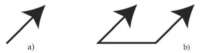
Fig. 11.1 The symbols used to indicate run-out tolerances: a circular run-out e b total run-out
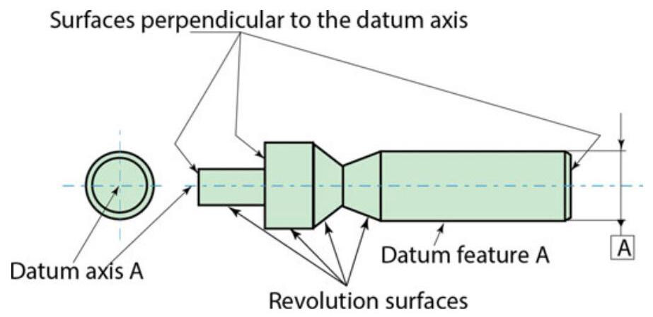
Fig. 11.2 Surfaces controlled by run-out tolerances
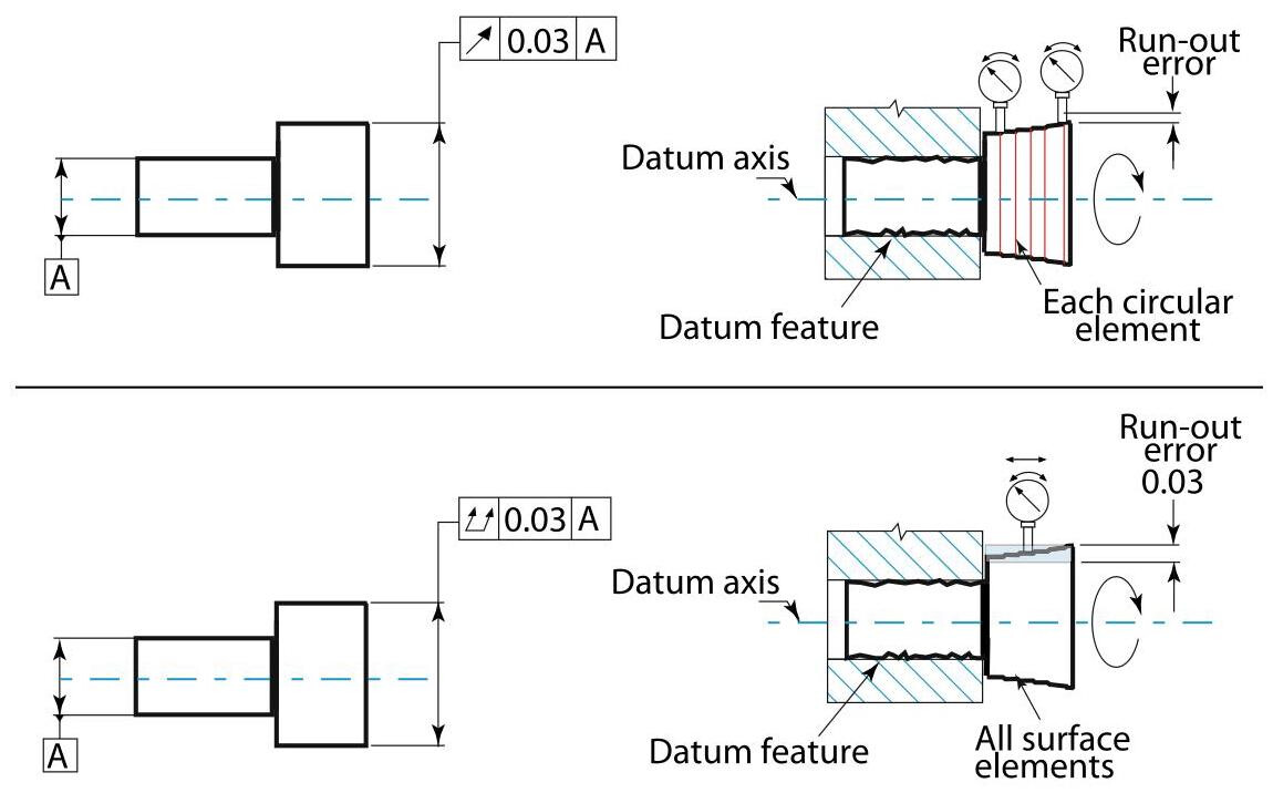
Fig. 11.3 Control of circular run-out and total run-out tolerances: circular run-out applies to each circular element independently, and each circular element must be within its 2D tolerance zone as the part is rotated {360}^{ \circ } . A total run-out applies to the entire surface simultaneously,and all the points on the surface must be within a common 3D tolerance zone as the part is rotated {360}^{ \circ }
In the total run-out case, the control applies to the entire surface simultaneously; the part is rotated by {360}^{ \circ } and the dial indicator is moved along the surface that has to be measured. In this case, the run-out error represents the difference between the maximum and minimum error indicated on the dial indicator at any position of the dial indicator. Total run-out provides a 3D control of all the surface elements of the considered feature and the tolerance applies simultaneously to all circular and profile elements of the surface.
The two run-out controls are both surface controls, and the MMR and LMR requirements are therefore not applicable.
The datum feature in run-out tolerances may be constituted by a single axis, two axes considered to be coincident or an axis plus a plane perpendicular to it.
11.2 Circular Run-Out
The control of a circular run-out may be achieved in both a radial and in an axial direction, and the tolerance zone is bi-dimensional. In a radial control, the extracted line, in each transversal section, perpendicular to datum axis A, should fall within two concentric, coplanar circles whose distance is equal to the tolerance; the centre of these circles should be on the datum axis. A circular run-out applies to each circular element independently; as already mentioned, the tolerance is applied independently to each measurement position of the workpiece subjected to a rotation of {360}^{ \circ } ,that is, each individual circular feature should have the circular run-out within the prescribed tolerance.
Figure 11.4 shows an example of circular run-out indications; the tolerance zone is limited, in each plane perpendicular to the axis, by two concentric circles placed at a distance that is equal to the prefixed tolerance and whose centres coincide with the datum axis. Sometimes referred to as TIR (Total Indicated Reading), run-out is the radial difference between two concentric circles at a datum point, and is designed to include all the points of the measured profile. In the case shown in Fig. 11.4, the radial run-out should be no greater than 0,05 mm on each measurement plane, during a complete rotation around datum axis A.
A circular tolerance zone may also be axial, and therefore allow the control of surfaces perpendicular to the axis, as shown in Fig. 11.5: the extracted line in each cylindrical section, whose axis coincides with that of datum axis D, should fall within two circumferences that are axially {0.1}\mathrm{\;{mm}} apart. In this case,a circular run-out also controls circular variations (wobble) of a plane surface.
A circular run-out can take place in any direction, or in a specified direction. In the former case, that is, when the direction is not specified, the measurement is performed perpendicular to the surface and the width of the tolerance zone is normal to the specified geometry, unless otherwise indicated, as shown in Fig. 11.6. Instead, if the circular run-out specification is indicated in a specified direction, the run-out refers to the specified direction. In this case, the use of a “Direction feature” symbol becomes essential, as shown in Fig. 11.7.
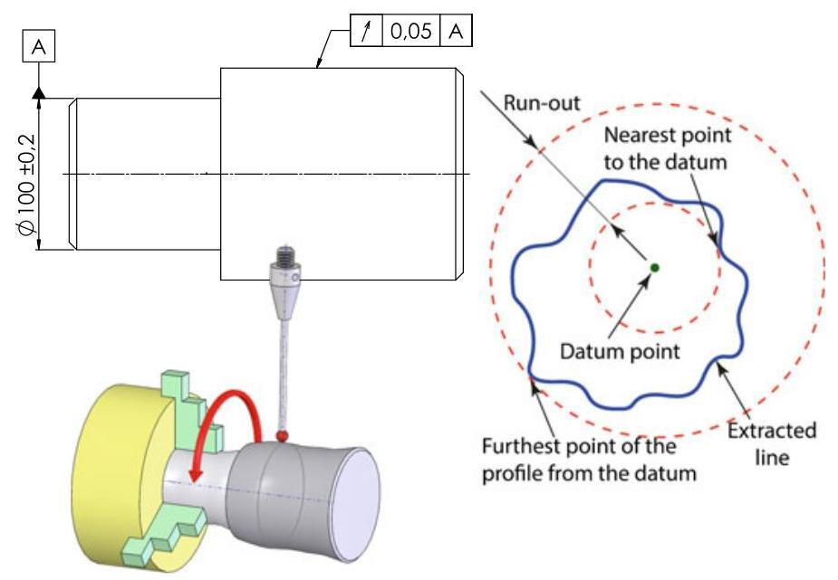
Fig. 11.4 Interpretation and inspection of a run-out tolerance. The extracted line, in each transversal section, perpendicular to datum axis A, should fall within two concentric, coplanar circles, whose distance is equal to the tolerance; the centre of these circles should be on the datum axis .
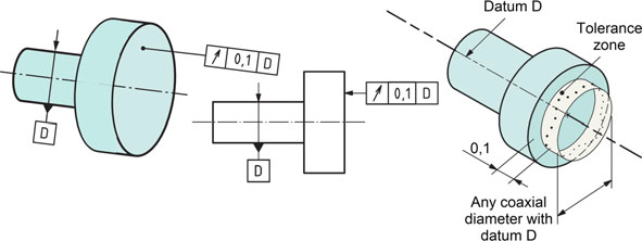
Fig. 11.5 Interpretation of an axial run-out: the tolerance zone is limited in any cylindrical section by two circles, at an axial distance of 0.1 mm apart, lying within the cylindrical section, the axis of which coincides with the datum
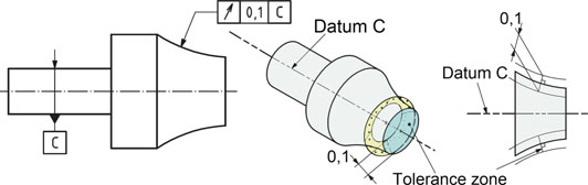
Fig. 11.6 The tolerance zone is limited within any conical section by two circles 0.1mm apart, the centres of which coincide with the datum. The width of the tolerance zone is always normal to the specified geometry, unless otherwise indicated
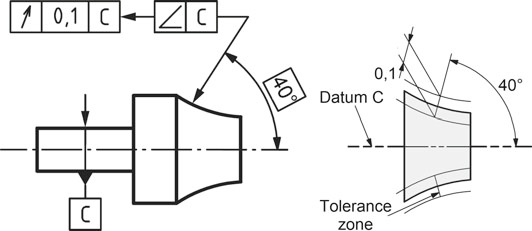
Fig. 11.7 Use of a “direction feature” symbol to indicate the measurement direction of the circular run-out error. The tolerance zone is limited within any conical section of the specified angle by two circles 0.1 mm apart, the centres of which coincide with the datum
11.3 Total Run-Out
In this case, a three-dimensional error zone is controlled and therefore, in the case of radial run-out, the extracted surface should fall within two coaxial cylinders, with a difference in radii equal to the run-out tolerance, the axes of which coincide with the datum axis (Fig. 11.8).
Figure 11.9 shows an example of the control of a tubular tolerance zone determined by two cylinders, and controlled by a complete displacement of the dial indicator (helicoidal movement), while the workpiece rotates around axis A; the difference between the maximum and minimum values shown on the dial indicator represents the total run-out error.
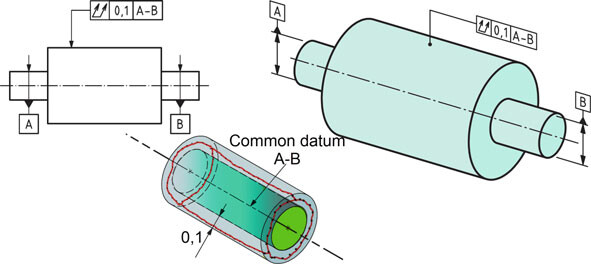
Fig. 11.8 The extracted surface should fall between two coaxial cylinders, with a difference in radii of 0.1 mm, and with the axes coincident with the common datum straight line A–B
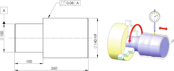
Fig. 11.9 Control of the total run-out with a dial indicator, which is moved in a helicoidal manner
It is also possible to control the total axial run-out in the same way as for the workpiece shown in Fig. 11.10; the extracted surface should fall within two parallel planes (at a distance that is equal to the tolerance) and perpendicular to datum axis D.
The run-out tolerance may also be controlled with two datums, as shown in Fig. 11.11. In this case, the sequence of indications of the datums becomes important: the component is controlled with a self-centring device, which is first placed on datum B and the jaws are then tightened.
Figure 11.12 shows a circular run-out control and a total run-out control through the total movement of a set of dial indicators on each round feature of the surface, while the workpiece rotates around the datum axis. The circular run-out error is obtained in the section with the largest variation (0.06 mm, less the assigned tolerance). The total run-out is the difference between the maximum reading (+0.05 mm) and theminimum reading (–0.08 mm) over the entire surface, that is, 0.13 mm, which is less than the run-out indicated in the design phase.
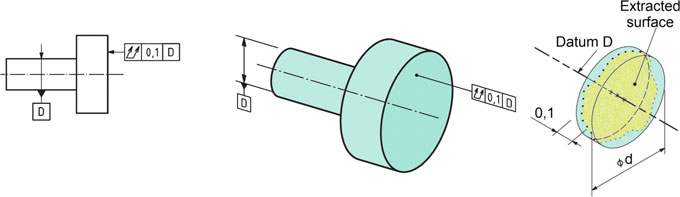
Fig. 11.10 Indications of a total axial run-out: the extracted surface should fall between two parallel planes 0.1 mm apart, which are perpendicular to datum axis D. A perpendicularity specification would have the same meaning
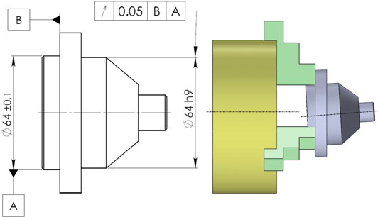
Fig. 11.11 Arun-out tolerancemay also be controlledwith two datums: the component is controlled by means of a self-centring device, which is first placed on datum B and the jaws are then tightened
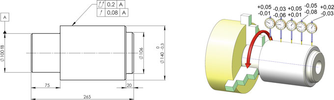
Fig. 11.12 An example of the contemporaneous control of a circular run-out and a total run-out with a set of dial indicators. The total run-out is the difference between themaximum reading (+0.05 mm) and the minimum reading (–0.08 mm) over the entire surface, that is, 0.13 mm, which is less than the run-out indicated in the design phase
11.4 Run-Out Control in the ASME Y14.5 Standards
In the Y14.5:2009 editions, run-out tolerances were explained in terms of a measurement method using a dial indicator. For consistency with the explanation method used for other tolerances, the explanation of run-out in ASME Y14.5:2018 is now based on the resulting tolerance zone. However, the definition of run-out tolerances has not changed.
-
Y14.5 2009 (Fig. 11.13): “Total runout provides control of all surface elements. The tolerance is applied simultaneously to all circular and profilemeasuring positions as the part is rotated 360 º about the datum axis. When verifying total runout, the indicator is fixed in orientation normal to and translates along the toleranced surface. The entire surface must lie within the specified runout tolerance zone (0.02 full indicator movement) when the part is rotated 360° about the datum axis with the indicator placed at every location along the surface in a position normal to the true geometric shape, without resetting of the indicator. The feature must be within the specified limits of size.”
-
Y14.5 2018 (Fig. 11.14): “Total Runout Tolerance Zone for Cylindrical Features: all surface elements shall be within a tolerance zone consisting of two coaxial cylinders with a radial separation equal to the tolerance value specified. The tolerance zone is constrained in translation (coaxial) to the datum axis.”
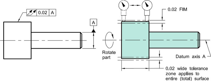
Fig. 11.13 In the Y14.5:2009 editions, run-out tolerances were explained by means of a measurement method using a dial indicator
In the ASME standards, the size tolerance controls the size as well as the form of the feature, and Rule #1 requires the perfect form at MMC. Run-out and size tolerances have combined effects on the size, form, orientation, and location of the toleranced feature (Fig. 11.15). Run-out tolerance and size tolerance values are based on the design requirements, and there is no requirement for run-out to be larger or smaller than the size tolerance.
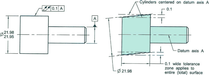
Fig. 11.14 In the new ASME Y14.5:2018 standard, the explanation of run-out is now based on the resulting tolerance zone
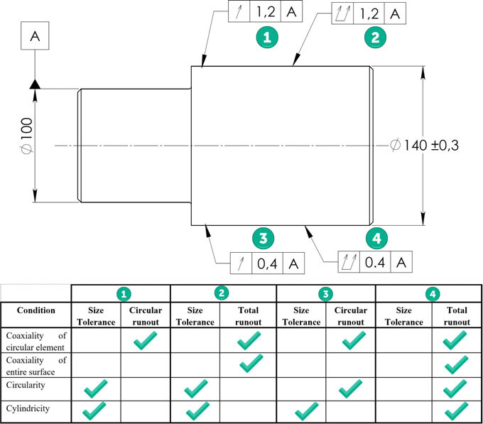
Fig. 11.15 Size and run-out tolerance effects
11.4.1 Run-Out on a Tangent Plane
The application of a run-out tolerance to a tangent plane has been added to the ASME Y14.5:2018 standard. A run-out tolerance may be applied to a tangent plane for one or more coplanar feature faces that are perpendicular to the rotation axis (Fig. 11.16).
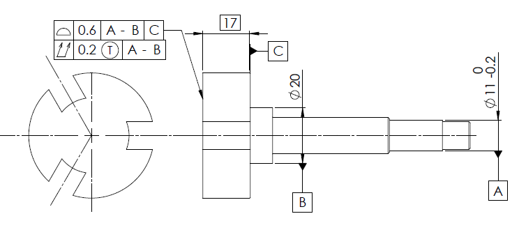
Fig. 11.16 Tangent Plane modifier applied to a total run-out control
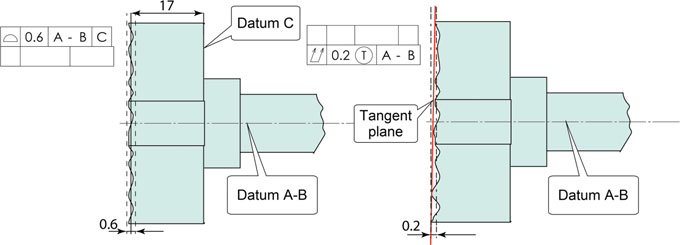
Fig. 11.17 The tolerance zone of the profile is located with reference to datum plane C and oriented to datum A–B, while the tangent plane, in contact with high points of the feature, should be within the 0.2 mm tolerance zone wide perpendicular to datum A–B
The requirements may also be specified using profile tolerances.
The extent of the tangent plane is circular with a radius equal to the distance from the rotation axis to the furthest point on the toleranced surface. In Fig. 11.17, the profile tolerance zone is located with reference to datum plane C and oriented to datum A–B, while the tangent plane, in contact with the high points of the feature, should be within the 0.2 mm wide tolerance zone perpendicular to datum A–B.
11.4.2 Run-Out Tolerance Application to an Assembly
The application of a run-out tolerance relative to an rotation axis, where the axis may not be a datum feature in an assembly, has been added to theASMEY14.5:2018 standard. When specified at an assembly level, run-out requirements may reference datum features that locate the assembly. The run-out tolerance is related to the rotation axis, while the axis is constrained at the basic angle relative to the datum reference frame, and the assembly is constrained in translation and rotation to the datum reference frame.
In the example in Fig. 11.18, the datum features constrain the orientation and location of the axis in order to ensure that the toleranced feature is within the specified run-out tolerance of the assembly. The interpretation of the run-out controls is illustrated in Fig. 11.19.
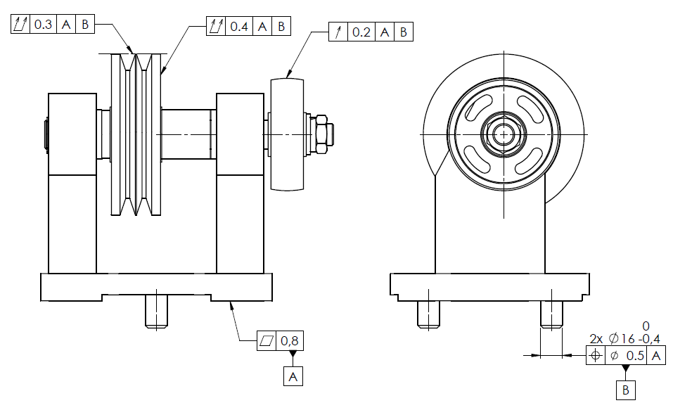
Fig. 11.18 Run-out tolerance applied to an assembly
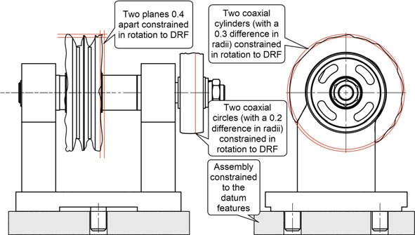
Fig. 11.19 Interpretation of the run-out controls of an assembly