Abstract Orientation tolerances (parallelism, perpendicularity and angularity) are used to control the orientation of a feature (surface or feature of size) with respect to one or more datums. When the orientation tolerances are applied to a feature of size and an MMR or LMR is added, the control of the orientation deviation no longer refers to the median line, but to the entire extracted feature (MMVC boundary), and it should not violate the MMVC virtual condition. The ISO and ASME standards use two different approaches to control the orientation of a feature of size: in order to orient a feature of size, the ISO standards define the concept of extracted median line or median surface. Instead, in the ASME standards, the axis or median plane is used to control the orientation of a feature of size.
8.1 Introduction
Orientation tolerances (parallelism, perpendicularity, angularity) control the orientation of a feature (surface or feature of size) with respect to one or more datums.
A parallelism control defines the deviation of a part feature from parallelism, and it is used for geometries that are at 180° with respect to another geometry.
A perpendicularity control defines the deviation of a part feature from perpendicularity,and it is used for geometries at 90° from each other.
An angularity control defines the deviation of a part feature with respect to a determined inclination,and it is used for geometries that are neither at 180° nor at 90° from each other.
8.2 Parallelism
A parallelism control defines the deviation of a part feature from parallelism, and it is used for geometries that are at 180°from each other. This type of error can be applied to a derived median line or a surface, and its symbol is two parallel dashes inclined at 60° .
The toleranced feature can be an integral feature or a derived feature. The theoretically exact dimension (TED) angles that are locked between the nominal toleranced feature and the datums should be defined by means of implicit TEDs(0°).
8.2.1 Parallelism of a Median Line Related to a Datum System
8.2.1.1 Parallelism of a Median Line Related to a Datum Axis
Since the tolerance value in the parallelism control in Fig. 8.1 is not preceded by the Ø symbol,and being an indicator of an orientation plane,the median line extracted from the upper hole should fall between two planes 0.1 mm apart, parallel to datum A, and with the orientation specified by datum B (Fig. 8.2).
In previous practice, as an alternative, the orientation of the tolerance zones was defined with a secondary datum (Fig. 8.3). However, a more rigorous parallelism control is obtained, as indicated in Fig. 8.4, when the extracted median falls between two pairs of parallel planes, which are parallel to datum axis A, and positioned 0.1 and 0.2 apart, respectively. The orientation of the planes that limit the tolerance zones is specified, with respect to datum plane B by the orientation plane indicators.
The tolerance zone in Fig. 8.5 is limited by a 0.3mm diameter cylinder,whose axis is parallel to datum A,because the tolerance value is preceded by the Ø symbol.
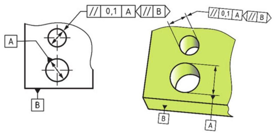
Fig. 8.1 Parallelism specification of a median line related to a datum axis; the planes that limit the tolerance zone are parallel to datum plane B, as specified by the orientation plane indicator
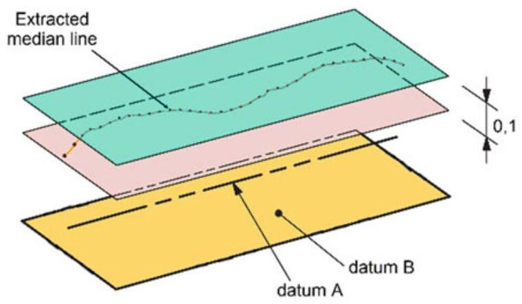
Fig. 8.2 Control of the extracted median line shown in the previous figure; in this case, the extracted median line of the upper hole should fall within two planes 0.1mm apart,parallel to datum A and with the orientation specified by datum B, as specified by the orientation plane indicator
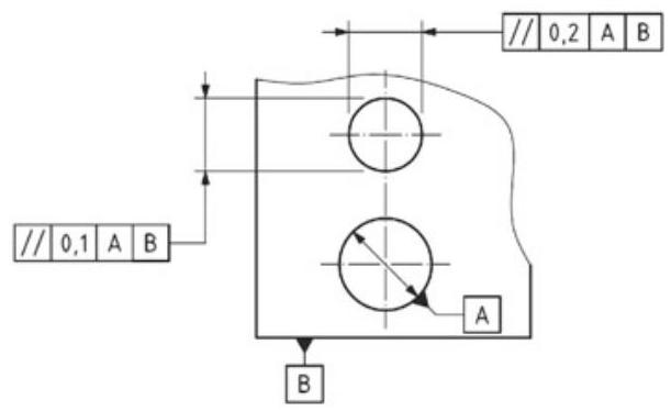
Fig. 8.3 A previous practice, alternative to the indication of the orientation plane shown in Fig. 8.1
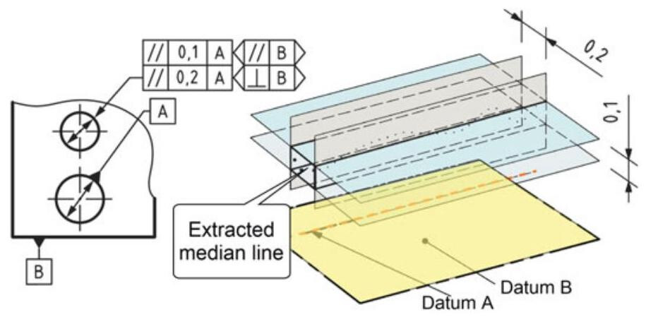
Fig. 8.4 Parallelism indication with two orientation plane indicators
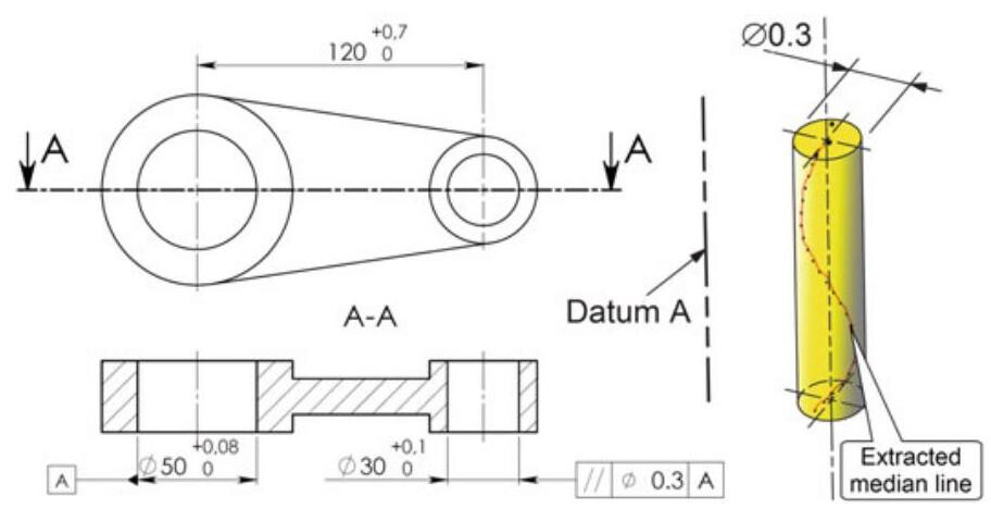
Fig. 8.5 The use of the Ø symbol defines a cylindrical tolerance zone parallel to the datum within which the extracted medium line should fall
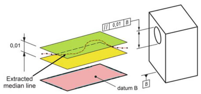
Fig. 8.6 If the tolerance value is not preceded by the Ø symbol,the extracted median line should fall between two parallel planes 0.01mm apart,which are parallel to datum plane B
8.2.1.2 Parallelism of a Median Line Related to a Datum Plane
A parallelism specification of a median line related to a datum plane, as shown in Fig. 8.6, where the extracted median line should fall between two parallel planes 0.01mm apart,which are parallel to datum plane B.
8.2.2 Parallelism of a Set of Lines on a Surface Related to a Datum Plane
Each extracted line in Fig. 8.7, parallel to datum plane B, as specified by the intersection plane indicator, should fall between two parallel lines 0.2 apart, which are parallel to datum plane A. The tolerance zone is limited by two parallel lines 0.2mm apart and oriented parallel to datum plane A, that is, the lines lying on a plane parallel to datum plane B.
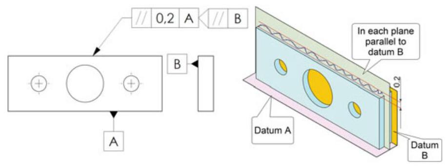
Fig. 8.7 Parallelism specification of a set of lines on a surface
8.2.3 Parallelism of a Planar Surface Related to a Datum System
Figure 8.8 shows a parallelism specification of a planar surface related to a datum plane; the upper extracted surface should fall between two parallel planes 0.4mm apart, which are parallel to datum plane A. It should be noted that the parallelism control also limits the flatness of the surfaces.
In this case, the principle of independency is also invoked by default for orientation tolerances, and the following rules are therefore valid (Fig. 8.9):
(1) the parallelism tolerance can have a higher value than the size tolerance value;
(2) each local dimension measured between two points should fall within the dimensional limits;
(3) the form deviations should fall within the parallelism tolerance values.
8.3 Perpendicularity
The toleranced feature controlled by a perpendicularity specification may be either an integral feature or a derived feature. The theoretically exact dimension (TED) angles that are locked between the nominal toleranced feature and the datums should be defined by means of implicit TED (90°). The control of perpendicularity (symbolised by two orthogonal dashes) is generally used to qualify a secondary or tertiary datum feature.
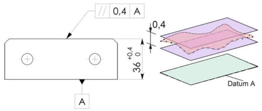
Fig. 8.8 Parallelism specification of a planar surface related to a datum plane
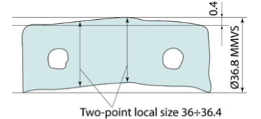
Fig. 8.9 Interpretation of the parallelism specification of the previous figure. The orientation tolerance is applied to a feature of size, and the principle of independency is thus invoked by default. Therefore, the parallelism tolerance may have a higher value than the size tolerance, and the form deviations (flatness in this case) should fall within the indicated tolerance values
8.3.1 Perpendicularity of a Median Line Related to a Datum System
In the case shown in Fig. 8.10, the extracted median line of the cylinder should fall between two pairs of parallel planes, perpendicular to datum plane A, and positioned 0.1mm and 0.2mm apart,respectively. The orientation of the planes that limit the tolerance zones is specified, with respect to datum plane B, by the orientation plane indicators. In short, the orientation of the planes is defined by two orientation plane symbols with respect to datum B. One couple of planes (0.1 mm apart) is perpendicular to datum B and the other ( 0.2mm apart) is parallel to datum B (Fig. 8.11).
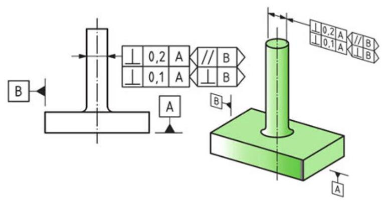
Fig. 8.10 Perpendicularity specification of a median line related to a datum system; the extracted median line of the cylinder should fall between two pairs of parallel planes, perpendicular to datum plane A, as indicated by the orientation plane indicators
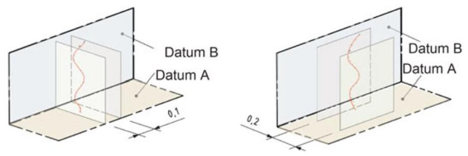
Fig. 8.11 The tolerance zone is limited by two pairs of parallel planes 0.1mm and 0.2mm apart, respectively, and perpendicular to each other. Both planes are perpendicular to datum A. One pair of planes is perpendicular to datum B and the other is parallel to datum B
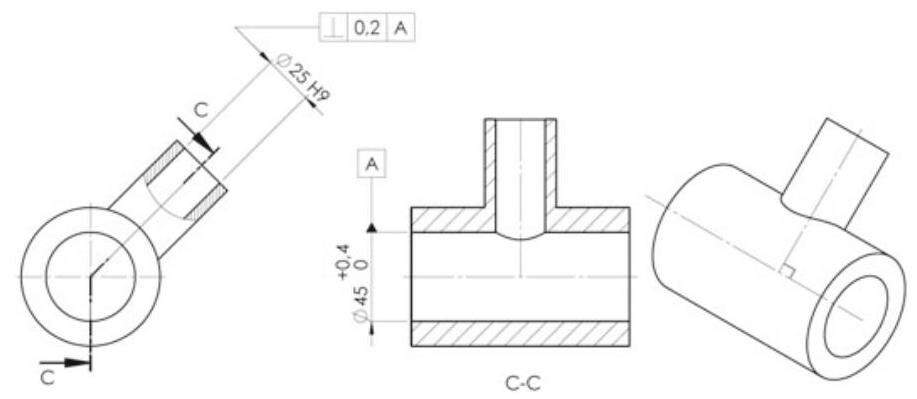
Fig. 8.12 Perpendicularity specification of a median line related to a datum straight line; the extracted median line of the 25mm diameter hole is controlled by a perpendicularity tolerance with respect to the axis of the horizontal hole, which is taken as a datum (it should be noted that, in the lateral view, the two axes are not on the same vertical plane)
8.3.2 Perpendicularity of a Median Line Related to a Datum Straight Line
As shown in Fig. 8.12,the extracted median line of the 25mm diameter hole is controlled by a perpendicularity tolerance with respect to the axis of the horizontal hole,which is taken as a datum. Since the tolerance value is not preceded by the Ø symbol,the extracted median line should fall between two parallel planes 0.2mm apart, which are perpendicular to datum axis A (Fig. 8.13).
8.3.3 Perpendicularity of a Median Line Related to a Datum Plane
The tolerance zone defined by the specification in Fig. 8.14 is limited by a 0.1mm diameter cylinder, whose axis is perpendicular to the datum A, because the tolerance value is preceded by the Ø symbol.
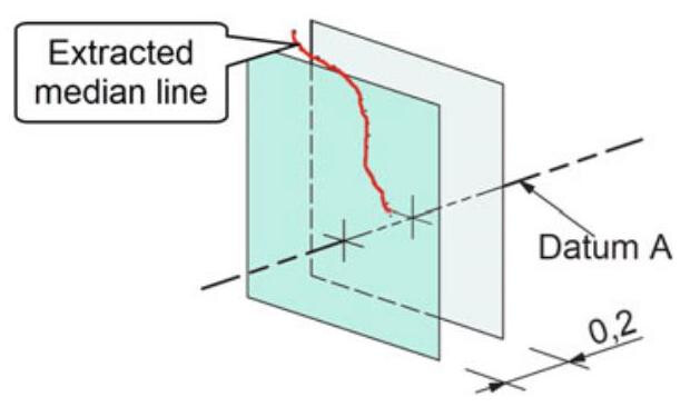
Fig. 8.13 Since the tolerance zone is not preceded by the Ø symbol, the tolerance zone is limited by two parallel planes 0.2 mm apart and perpendicular to datum axis A
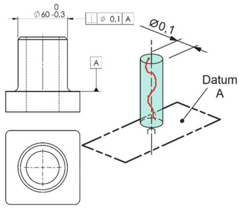
Fig. 8.14 Perpendicularity tolerance applied to a cylindrical feature of size utilising the Ø symbol
8.3.4 Perpendicularity of a Planar Surface Related to a Datum Plane
The extracted surface in Fig. 8.15 should be contained between two parallel planes 0.1mm apart,which are perpendicular to datum plane A. Again,in this case,flatness is implicitly controlled. The rotation of the tolerance zone around the normal of the datum plane is not defined with the indication given in Fig. 8.15, and only the direction is specified. The assembly and control procedures of the workpiece are also illustrated in Fig. 8.16: the component is free to rotate around a horizontal axis, and this instability could influence the verification of the perpendicularity deviation. In order to avoid this problem, the perpendicularity tolerance may be prescribed with two datums.
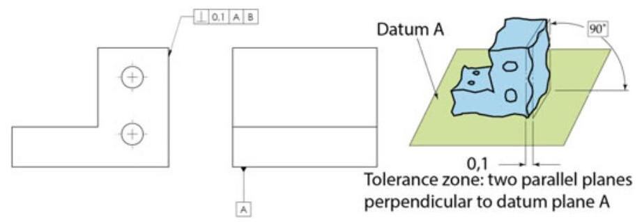
Fig. 8.15 Perpendicularity specification of a planar surface related to a datum plane
As a result, in the case of Fig. 8.17, the perpendicularity tolerance is applied with two datum planes, because the assembly of the workpiece implies the alignment with surface B; the control takes place by first placing the workpiece on the primary plane and then on the secondary plane (Fig. 8.18).
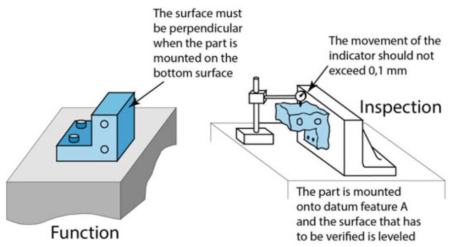
Fig. 8.16 Functional requirements and inspection of a workpiece subject to a perpendicularity requirement
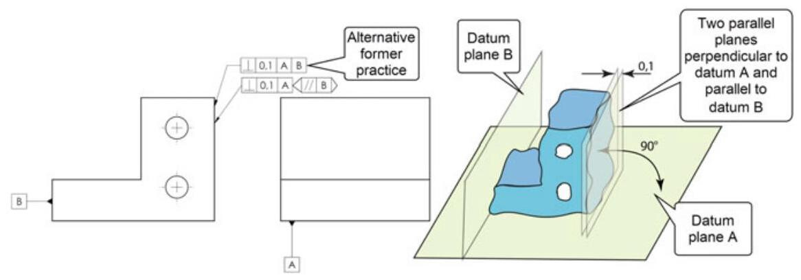
Fig. 8.17 Drawing of a workpiece subject to a perpendicularity requirement with two datum planes. The extracted surface should fall between two parallel planes 0.1mm apart,which are perpendicular to datum plane A and parallel to datum B, as specified by the orientation plane indicator
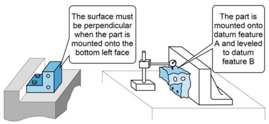
Fig. 8.18 Functional requirements and inspection of a workpiece subject to a perpendicularity requirement related to two datum features
8.3.5 Perpendicularity (MMR) Applied to a Feature of Size
When the perpendicularity tolerance is applied to a cylindrical feature of size and a maximum material requirement (MMR) is added, as shown in Fig. 8.19, the control of the orientation deviation no longer refers to the median line, but to the entire extracted feature (MMVC boundary), and it should not violate the MMVC virtual condition of 60.1mm,which is calculated by summing the maximum material size (60mm) with the perpendicularity geometrical tolerance (0.1mm).
The MMVC represents the most unfavourable mating condition by which a designer is able to ensure full functionality and interchangeability of the produced parts, and all at a minimum cost.
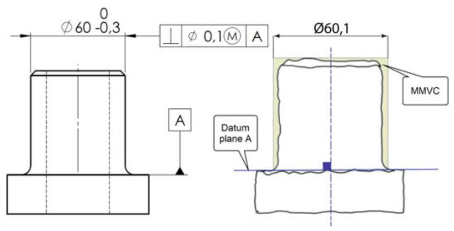
Fig. 8.19 Perpendicularity tolerance (MMR) applied to a feature of size: the control of the orientation deviation no longer refers to the median line, but to the entire extracted feature, which should not violate the MMVC virtual conditions of 60.1mm
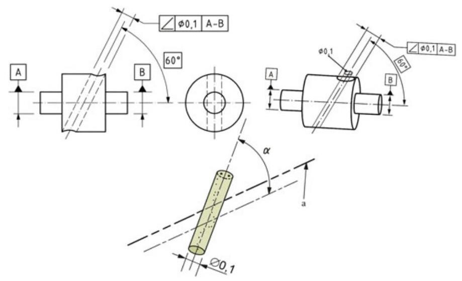
Fig. 8.20 Angularity specification of a median line related to a datum straight line; the extracted median line should be contained within a 0.1 diameter cylinder, which is inclined at a theoretically exact angle of 60° with respect to the common datum straight line A-B
8.4 Angularity
Angularity represents the conditions of a surface, or derived median line, that is at a determined angle (other than 90° and 0° ) with respect to a datum. The theoretically exact dimension angles that are locked between the nominal toleranced feature and the datums should be defined by means of at least one explicit TED. Additional angles may be defined by means of implicit TEDs 0° or 90° .
8.4.1 Angularity of a Median Line Related to a Datum Straight Line
In the case of Fig. 8.20, the extracted median line should fall within a 0.1 diameter cylinder,which is inclined at a theoretically exact angle of 60° with respect to the common datum straight line A-B. The considered line and the datum line are not on the same plane.
8.4.2 Angularity of a Median Line Related to a Datum System
This is the case shown in Fig. 8.21, where the extracted median line should be within a 0.1mm diameter cylindrical tolerance zone that is parallel to datum plane B and inclined at a theoretically exact angle of 60° with respect to datum plane A. If the tolerance value is preceded by the Ø symbol,the tolerance zone is a cylinder with the indicated diameter, and with the axis inclined with respect to the datum feature and parallel to secondary datum B (Fig. 8.22). An alternative to the specification with two datums is the orientation plane indicator.
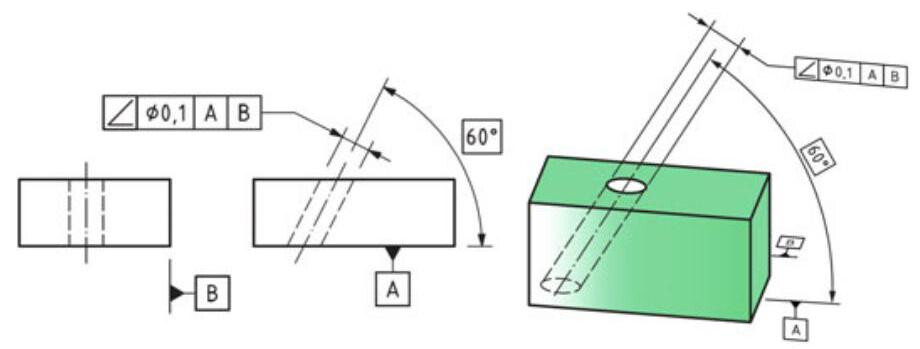
Fig. 8.21 Angularity specification for an extracted median line related to a datum system. The presence of the theoretically exact dimension (TED) can be noted for the angle
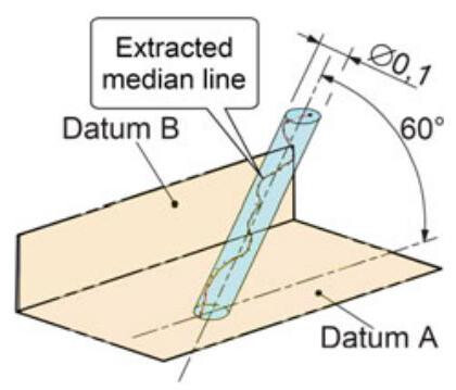
Fig. 8.22 Interpretation of the tolerance zone of the previous figure. The extracted median line should fall within a cylindrical tolerance zone (of 0.1mm diameter), parallel to datum B and inclined by 60° with respect to datum plane A
8.4.3 Angularity of a Planar Surface Related to a Datum Plane
The tolerance zone in Fig. 8.23 is composed of two planes 0.1mm apart and inclined by 30° with respect to datum plane A. The entire surface should fall within the tolerance,and this means that there is also a flatness control of 0.1mm . The control is achieved by mounting the part onto the gauge equipment, using a sine plate set at the basic angle to make the toleranced surface parallel to the surface plate. A dial indicator is used to verify that the surface elements are within the angularity tolerance zone (Fig. 8.24). Angularity does not control the position of the tolerance zone, for which it may translate in any direction, but the zone must remain oriented to datum plane A at an angle of 30° . However,the rotation of the tolerance zone around the normal to the datum plane is not defined in the drawing, thus making the inspection difficult and expensive.
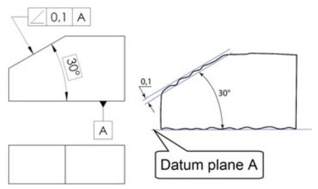
Fig. 8.23 Angularity specification of a planar surface related to a datum plane. The tolerance zone is limited by two parallel planes 0.1 mm apart and inclined, at the specified angle, to datum A
In all the illustrated examples, the angular dimensions should be framed, as they represent the theoretically exact dimensions that are not subject to general tolerances and which define the theoretical inclination of the tolerance zone with respect to the datum.
Figure 8.25 shows the same workpiece as Fig. 8.23, with indication of two datum planes; the only difference from the previous case pertains to the control modality, in that, in order to avoid instability problems, the workpiece is first orientated with respect to primary plane A and then aligned according to datum plane B.
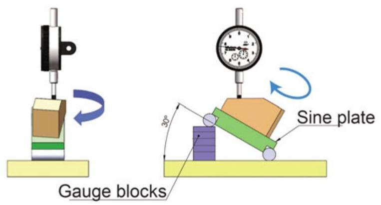
Fig. 8.24 Control with a piece of equipment called a sine plate set. It should be noted that rotation around an axis perpendicular to the datum is possible, and this leads to difficulty in the control
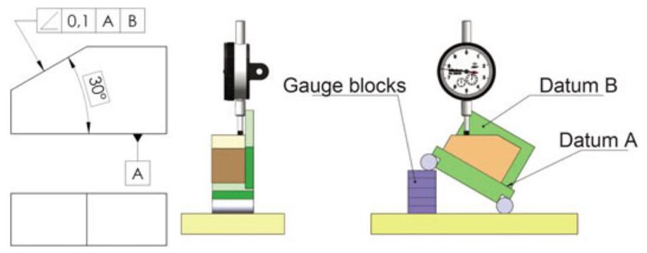
Fig. 8.25 Angularity specification of a planar surface with respect to a datum system
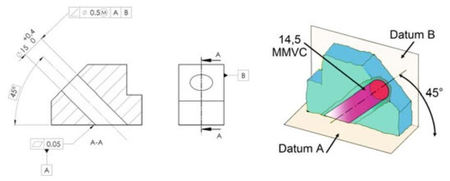
Fig. 8.26 Effect of the maximum material requirement applied to an angularity tolerance. In this case, the extracted median line is not controlled, but the edge of the hole is, and this edge should not violate the MMVS of 14.5mm ,whose axis is inclined by 45° with respect to datum A
8.4.4 Angularity (MMR) Applied to a Feature of Size
Figure 8.26 shows the effect of a maximum material requirement (MMR) applied to an angularity specification. In this case, the extracted median line is not controlled, but the MMVC (MMVS=14.5mm) of the hole is. The hole boundaries should not violate the MMVC,whose axis is inclined by 45° with respect to datum A. Datum B plays the role of stabilising the angularity verification process.
8.5 Orientation Tolerances in the ASME Standards
As mentioned in the previous sections, the ISO and ASME standards use two different approaches to determine or simulate an axis, above all for orientation tolerances: in fact, as has already been seen, in order to orient a cylindrical feature, the ISO standards define the concept of derived median line (or extracted median line). Instead, in the ASME standards, the axis of the unrelated AME (smallest circumscribed cylinder) is used to verify the perpendicularity control (Fig. 8.27).
In the ASME standards it is emphasised that orientation tolerances does not control the location of features, and when specifying an orientation tolerance, consideration should therefore be given to the control of orientation, as already established through other tolerances, such as position, run-out, and profile controls (Fig. 8.28).
ISO 1101 has recently introduced the new tangent plane symbol, which was previously present in ASME Y14.5 M of 1994. When a tangent plane symbol is specified with a geometric tolerance, a plane in contact with the high points of the feature should fall within the tolerance zone established by the geometric tolerance. In this case, the form of the toleranced feature is not controlled by the geometric tolerance and some points of the toleranced feature may lie outside the tolerance zone (Fig. 8.29).
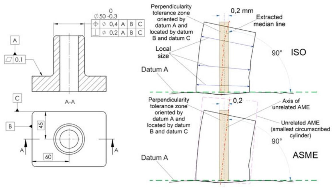
Fig. 8.27 The ISO standards define the concept of extracted median line in order to control the orientation. Instead, the ASME standard controls the orientation of the axis of the smallest circumscribed cylinder and, at the same time, the cylindrical feature should have the perfect form at the maximum material condition
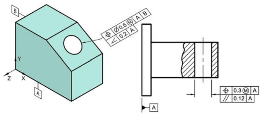
Fig. 8.28 Orientation tolerances does not control the location of features, and it is therefore necessary to specify other location controls
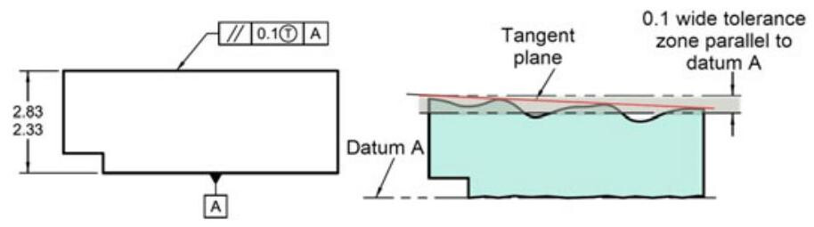
Fig. 8.29 Control of the parallelism of a planar surface with a tangent plane modifier. In this case, the form of the toleranced feature is not controlled by the geometric tolerance, and some points of the toleranced feature may lie outside the tolerance zone