1. Body Parts Development Process
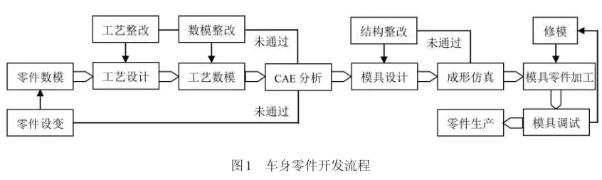
In the development process of body parts, the introduction of CAE forming simulation analysis can shorten the mold manufacturing cycle and improve part forming quality. The body parts development process is shown in Figure 1. From the part design to the mass production of parts, CAE forming simulation is a key step, serving as a virtual verification of the stamping process and mold structure design. Based on the verification results, adjustments and optimizations are made to the part design, process plan, and mold structure, minimizing the quality risks during mold debugging. During the mold debugging phase, since the actual on-site conditions may differ from the process parameters used in the simulation analysis, local modifications to the mold are made to address hidden defects in the part, ensuring stable production of the part.
2. Case Study of Front Windshield Lower Panel
Taking the front windshield lower panel of a specific vehicle model as an example, special process design adjustments were made based on its structural characteristics and forming simulation results. During the initial mold debugging, surface slip lines, dents, and other quality defects appeared on the part’s outer surface. By analyzing the causes of these issues, corresponding corrective measures were formulated and verified, resulting in the successful debugging and production of qualified parts.
2.1 Part Feature Analysis
The front windshield lower panel of a certain vehicle model is shown in Figure 2, with a material of DC56D+Z and a thickness of 1.0 mm. The blank size is 1870mm × 410mm. The feature analysis of the part is as follows:
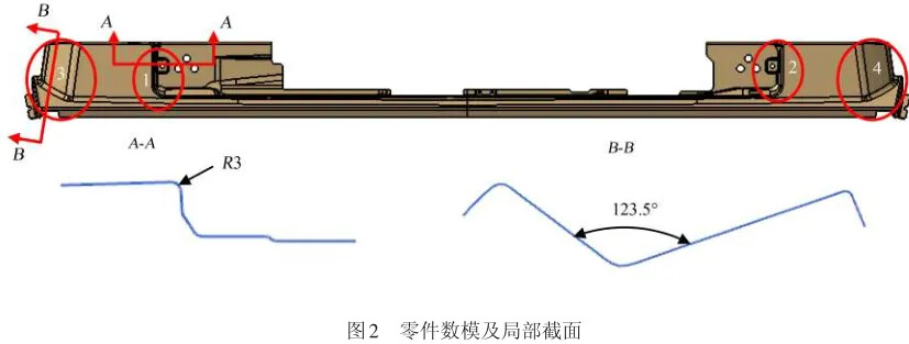
- The middle part (marked as 1, 2) has a transition radius of R3mm for the corner, and the sidewall draft angle is only 1.5°. Direct deep drawing poses a risk of cracking, requiring a pre-drawing process and final shaping.
- The two ends (marked as 3, 4) have a deep V-shape. Due to the part’s aesthetic requirements, the three radiused corners must all undergo deep drawing. The analysis of this stamping process is as follows:
- If the material flow into the end regions is too large, excessive material will lead to unflattened wrinkles in the final part.
- If the material is too tightly constrained, limiting material flow into the end regions will inevitably cause cracks in the sharp corner areas. These two factors, related to controlling material flow and speed during stamping, present challenges in the forming process.
- The process design for this part is as follows: deep drawing → trimming/side trimming/punching → trimming/side trimming/side punching → flanging → shaping. The final forming quality of the part mainly depends on the quality of the deep drawing process.
2.2 Deep Drawing Die Part Design
The die part design for the deep drawing process was carried out based on stamping process knowledge and experience.
-
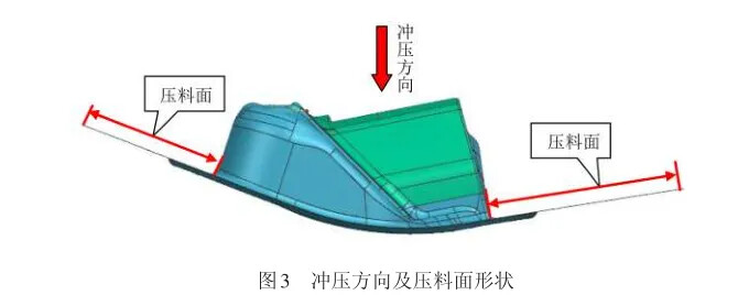
The stamping direction was determined with the basic principle that the highest points on both the front and rear sides of the part make contact with the die simultaneously. The pressure plate surface design follows the part’s profile, transitioning smoothly, as shown in Figure 3.
-
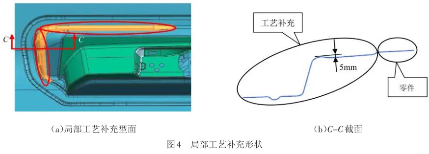
During the process adjustment design, to prevent surface wrinkling when the material flow speed is too fast at both ends, a deep drawing threshold was designed at the convex mold’s corner (5mm at the highest point with a uniform transition) to increase material resistance and ensure sufficient material flow towards the final stage of stamping, as shown in Figure 4 (with the elliptical marks indicating the threshold design).
-
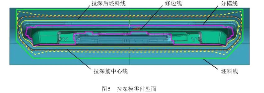
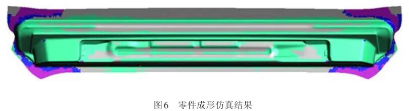
Further refining the design, reasonable placement of deep drawing ribs was carried out to optimize material flow speed, part stiffness, and quality. The deep drawing die part profile is shown in Figure 5. Using CAE software to simulate the forming process provided the optimal simulation analysis results (formability, thinning rate, thickening rate, impact line, slip line, and principal strain), ensuring that the part’s appearance was free of wrinkles and cracks in the sharp corners. The simulation results are shown in Figure 6. Based on these results, the deep drawing process parameters were determined to be: forming force 3200 kN, blank holder force 500 kN, and blank holder stroke 150mm.
2.3 Debugging Issues and Cause Analysis
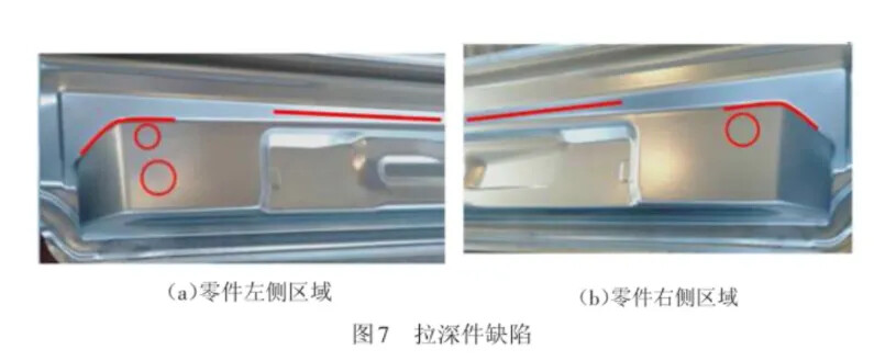
Based on the process plan and simulation analysis-derived process parameters, mold debugging was carried out. Initially, the blank’s edge trimming size and blank holder force (finally determined to be 720 kN) and forming force (final value of 4400 kN) were adjusted to ensure that the part’s outer surface did not show cracking or wrinkling. However, slip lines appeared on the top edges of the part, and there were localized dents and marks on the lower concave corners. Figure 7 shows the defects on the deep-drawn part: straight lines indicate slip lines, curved lines indicate corner dents, and circular marks indicate surface impressions.
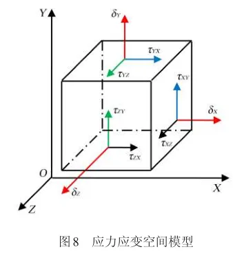
An analysis of the part’s structural features revealed that, due to variations in deep drawing depth, the material feeding speed was uneven on both sides of the edge. Faster feeding on the outer side caused slip lines on the inner side of the edges, with deeper areas showing more pronounced slip lines. The material at the edge is subjected to both tensile and shear stresses during forming, with the stress-strain model at a certain point shown in Figure 8. When the stress difference between two directions is large, displacement occurs, leading to the formation of slip lines. The surface impressions and dents on the part during forming were caused by the roughness and poor mating of the mold surfaces and localized hard points.
2.4 Corrective Measures and Effect Verification
To address the forming defects, the mold parts were first polished, and the surface was smoothed to a mirror finish with a roughness value of Ra0.8μm. Before the secondary machine debugging, the mold was further run-in, and hard contact points were polished. Ultimately, the surface contact between the inside of the deep drawing ribs and the die cavity was ensured to reach a 90% or higher matching rate, with tight contact at the convex corners and a small gap at the concave corners, while the curved edges were densely contacted.
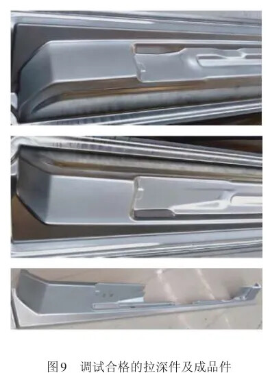
During mold debugging, the material feeding speed was adjusted by increasing the blank holder force on the outer edge of the part, with greater pressure applied to areas with larger forming depths. By ensuring more uniform feeding on both sides, the sliding distance at the edges was reduced to within one corner radius. Figure 9 shows the successfully debugged deep-drawn part and the finished product.