The SD card, which many of us have used, automatically locks into place when inserted, and pops out with a press. But how is this function achieved?

In daily life, the mobile phone storage card slot mechanism is simple yet quite classic. This mechanism is a classic application of springs and a “maze groove” design.
Inside, there’s a sliding groove with a separation block at the top. When the card is inserted, it pushes a plastic part down. The steel wire, which has hooks at both ends and was originally inside the groove, starts moving upward. When it reaches the top, the separation block causes the steel wire to tilt. After passing that point, the steel wire, due to its elasticity, moves inward and settles into a small recess just above the separation block. This completes the first pressing action. When pressed again, the steel wire is moved to the other side, which ensures that the wire can smoothly return to the bottom, completing the ejection action.

This mechanism is a clever application of springs and a “maze groove”. Each turn is designed with a step, so that the pull rod can only move along a specific path and cannot move in reverse. This PUSH-PUSH structure works similarly to the mechanism in a ballpoint pen.
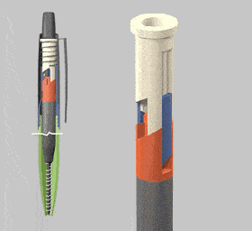
As shown in the diagram above, this mechanism consists of three parts: the black push rod, the yellow turntable, and the blue sliding groove. The red part represents a partial view of the sliding groove. The supporting spring is not illustrated, but it is important to note that the turntable always has an upward force pressing it. When pressure is applied to the push rod, it moves along the sliding groove, pushing the turntable down. When the turntable disengages from the sliding groove, the pointed features at the push rod’s head generate radial force at the contact point with the turntable’s slope, forcing the turntable to rotate and re-engage with the sliding groove. This action is repeated every time the push rod is pressed.
There are two states of engagement between the turntable and the sliding groove: one where the turntable is embedded in the groove, as shown in figure 8, and the other where the turntable is not, as shown in figure 4. These two states alternate, mimicking the retraction and extension of the pen’s ink cartridge.