“Image to Curve” Plugin in COMSOL Multiphysics
The “Image to Curve” plugin is a product extension in COMSOL Multiphysics that allows you to import an image into COMSOL as a starting point for simulation analysis. With this plugin, you can convert the contours of the imported image into interpolation curves and then transform them into a part of the model geometry. In this article, we will demonstrate how to use this feature.
Introduction to “Image to Curve” Plugin
The following images show the different steps involved in creating a swept mesh based on a photo that uses black marking lines to draw the contours. In this example, a 3D model is created by stretching a 2D geometric shape.
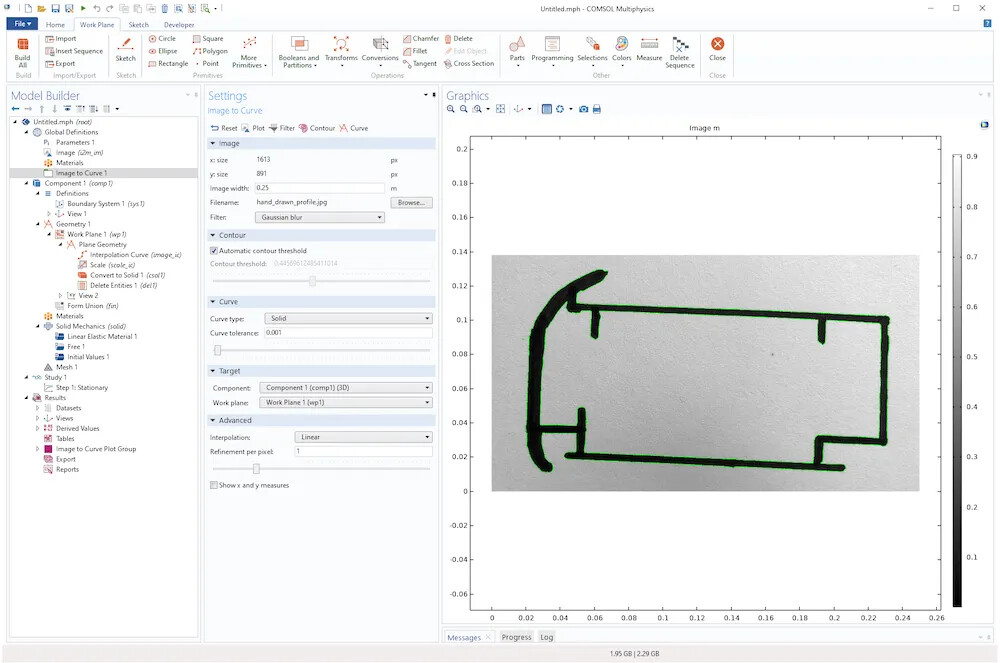
Imported Photo: A photo taken with a smartphone, with black marking lines outlining the contours, and green fine lines showing overlaid contour lines.
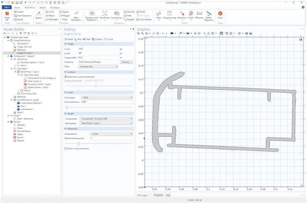
Image Conversion to Model Geometry: After removing irrelevant domains generated during the image-to-geometry conversion process, the resulting 3D geometry contours are obtained.
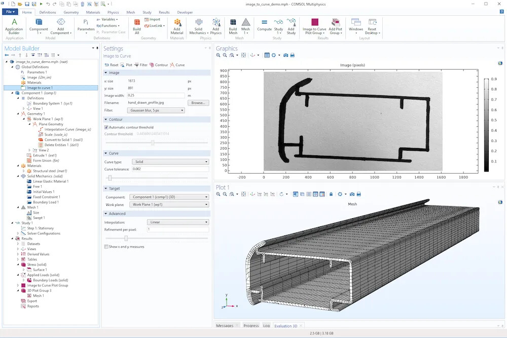
Swept Mesh Based on Black Marking Line Contours: The swept mesh is generated from the contours created with black marking lines.
Enabling the “Image to Curve” Plugin
-
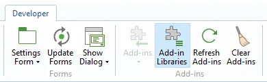
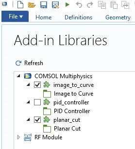
First, select the Developer Tools tab in the model builder, click on the Plugin Library, and enable the “Image to Curve” plugin from the library.
-
From the list, select the “Image to Curve” checkbox to enable the plugin.
-
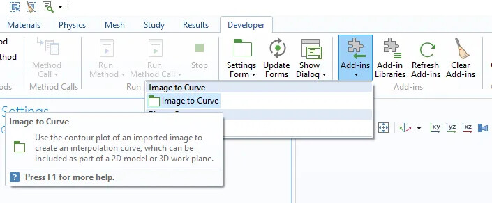
Once enabled, you will see the “Image to Curve” plugin displayed in the interface.
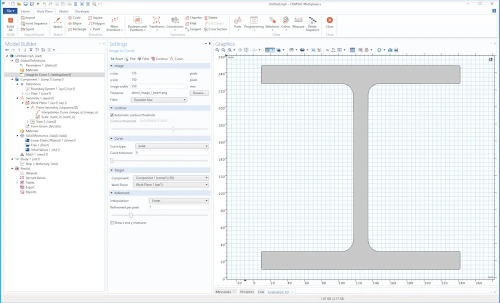
“Image to Curve” Settings Window
The “Image to Curve” plugin settings window is shown below. The top of the window contains 5 toolbar buttons and 5 sections with different settings.

The toolbar buttons include:
![]()
- Reset: Resets all values to the default settings.
- Drawing: Renders the original imported image without any filters.
- Filter: Renders the filtered image using the filter specified in the Image section.
- Contour: Draws the image contours using the threshold settings specified in the Contour section.
- Curve: Creates interpolation curve nodes in a 2D geometry sequence or 3D work plane.
Image Section
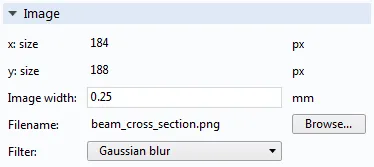
To import an image, click the Browse button in the Image section of the plugin settings window to open the file browser and select the image to import.
- Supported formats include .png, .jpg, .jpeg, .bmp, and .gif.
- For high-quality model geometry creation, the imported image should ideally have a light background with dark shapes, or a dark background with light shapes.
- When importing an image, it is converted to grayscale, and the image’s dimensions in pixels (x and y), width in current length units (as determined by the geometry node), filename, and filter settings will be displayed.
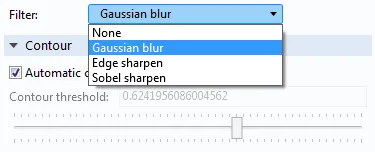
By adjusting the image width value, you can modify the final geometry structure size. You can also adjust this setting later by adding scaling feature nodes in the geometry sequence. The filter options include some blurring and sharpening filters to reduce noise or enhance edges in the imported image.
Contour Section
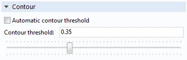
By default, the contour curve is automatically placed where the pixel intensity level is close to the average threshold in the filtered image. If you need to manually control the contour threshold, clear the “Auto Contour Threshold” checkbox.
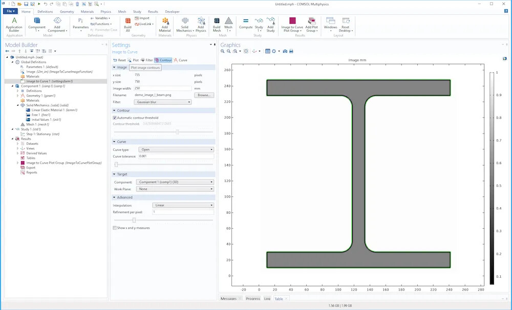
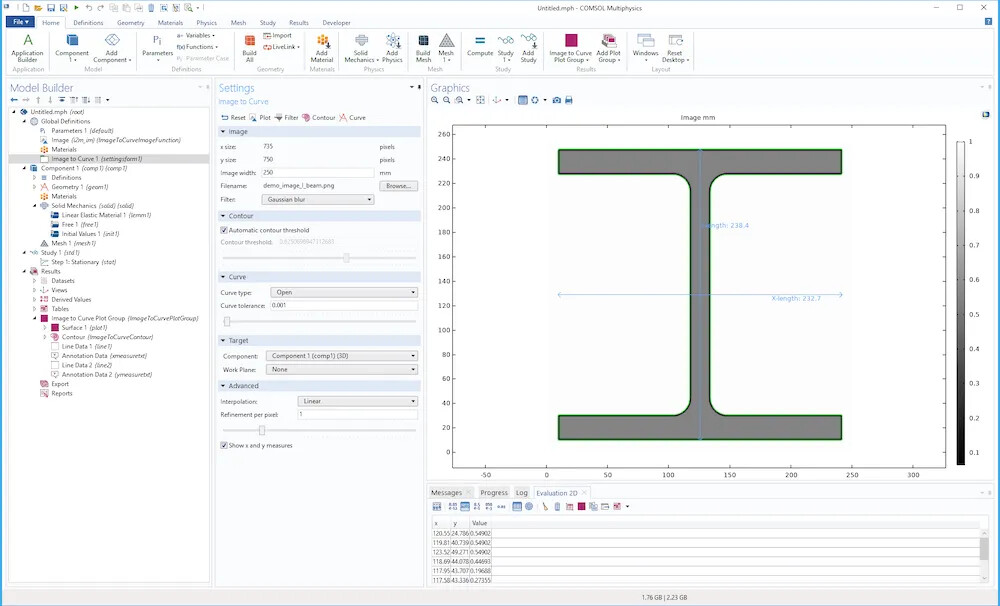
Click the Contour button in the toolbar to visualize the contour curve and image. The following is an example of a contour line (green) from an imported I-beam image.
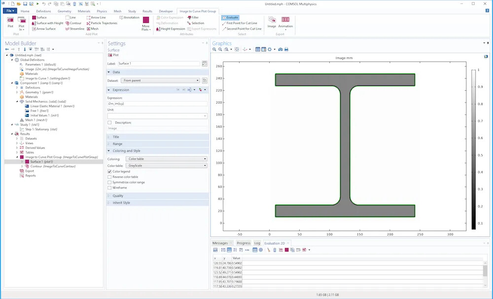
To inspect pixel values, select the surface nodes in the “Image to Curve” group and click on the graphical window. The pixel values and coordinates will be displayed in a 2D computation table.
Curve Section
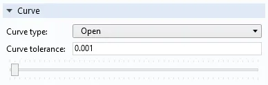
Click the Curve button in the toolbar to generate interpolation curve nodes in the 2D geometry sequence or 3D work plane. By default, the curve type is set to open, but you can change it to closed or solid. The curve tolerance setting determines how close the curve should be to the contour curve.
The following image shows an example of an I-beam, where the curve type is set to solid and the curve tolerance is set to 0.0.
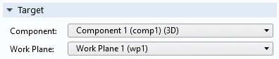
Target Section
In the Target section, you can specify the geometry sequence for which interpolation curve nodes should be created. You can specify the model components and, for 3D geometry, specify the work plane.
Advanced Section
In the Advanced section, you can change the interpolation method used for visualizing the image, choosing between linear and nearest neighbor interpolation. The pixel refinement setting determines the number of grid cells representing each pixel in the image: values less than 1.0 mean fewer interpolation points than the pixels in the image, and values greater than 1.0 mean the grid will oversample the image.
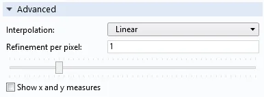
The checkbox for showing x and y measurements allows you to control whether to display the dimensions of the contour curve.
Help Section
If you need dynamic help related to the plugin, click on the “Image to Curve” node in the model tree, then click on the question mark icon in the top right corner of the COMSOL Desktop® user interface (similar to how you access documentation for other settings windows).
Example of Converting an Image to Geometry Model
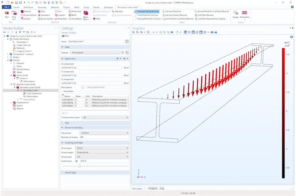
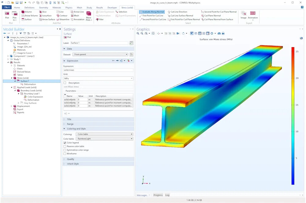
The example model file image_to_curve_h_beam.mph contains a simple structural analysis with a distributed load, as shown below. The distributed load is based on the geometry formed by stretching the image geometry.
Additionally, the file hand_drawn_image_geometry_and_mesh.mph contains geometry and swept mesh based on the black marking line contours described earlier. This model not only demonstrates how to use the “Image to Curve” plugin but also shows how to remove irrelevant domains created during the image-to-geometry conversion process.
Note that you can continue to use all the geometry modeling features provided by COMSOL, such as combining with other geometric parts or drilling holes, to further process the 2D or 3D extruded geometry. The mesh shown in the examples is a swept mesh, but you can also use unstructured tetrahedral or triangular meshes.