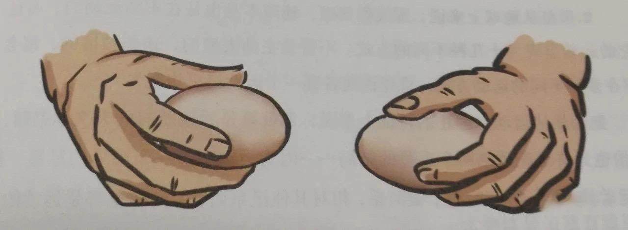
Recently, I saw a game where two boiled eggs are crashed together, and the one that breaks first loses. At first glance, it seems like a game of pure luck, but upon closer examination, I found it contains many interesting principles of mechanics! How to always win at ‘egg crashing’? CAE simulation has the trick!
Red-dyed peach blossoms, snow pressing on the pear trees, delicate eggs vying for victory. This year, it’s not the clear cold food festival, but secretly the swing has its moment.
— Tang Dynasty, Yuan Zhen, "Cold Food Night
Hundreds of years ago, the American magazine ‘Science and Invention’ reported that through multiple experiments, it was found that the egg that actively crashes into another egg tends to break more often. This is because the internal materials of the moving egg compress the shell upon impact, causing it to break.
Is it true that the egg that actively crashes into another egg is more likely to break? This article intends to use Ansys Workbench’s explicit dynamics analysis module LS-DYNA to perform a mechanical analysis of both eggs involved in ‘egg crashing’ and propose strategies with a higher probability of winning and high feasibility. The detailed steps are as follows.
1. Build the geometric model.
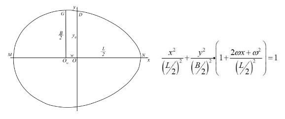
As stated in literature [3], the egg-shaped contour can be drawn based on the general formula of the Höger-Scheffler model, as shown in the figure below. Here, L is the length of the egg, B is the width of the egg, and w is the distance from the widest part to the midpoint of the egg length. By measuring these three parameters of the egg, its geometric shape can be reconstructed.
Use SolidWorks to complete the egg modeling, including the eggshell, egg white, and yolk. According to literature [4], the length L is 60mm, the width B is 44mm, and the distance w is 10mm, which are used to establish the basic shape of the egg. The eggshell thickness is set to 0.35mm, and the yolk is approximated as a sphere with a radius of 10mm.
2. Create the analysis workflow
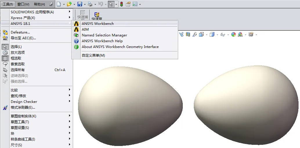
To associate Ansys Workbench with SolidWorks, click on “Tools” in the SolidWorks menu bar and select Ansys Workbench to transfer the model to the Geometry section of Ansys Workbench. Set the units to mm, right-click Geometry to enter the Design Modeler (DM) interface, right-click Attach1, and select Generate to create the geometry model.
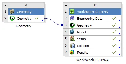
When dealing with transient, large strain, large deformation, collision, and complex contact problems, explicit dynamic solvers can effectively meet the simulation requirements. Click on “Extensions,” open the interface, check the appropriate options, and then click “Close.” Drag and drop “Workbench LS-DYNA” onto “Geometry” to create a project analysis workflow, as shown in the figure below.
3. Add material properties
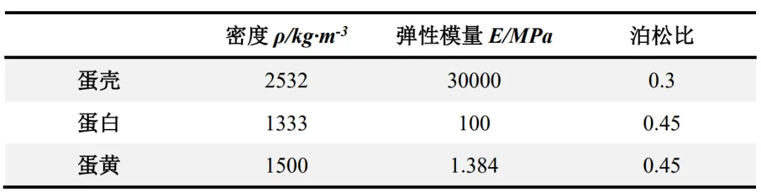
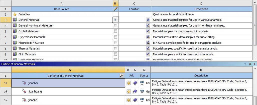
Double-click “Engineering Data” to enter the editing environment. Right-click the blank area and select “Engineering Data Sources.” Check the box next to “General Materials,” right-click any material in the list below, select “Duplicate,” rename it, and set the material properties according to the table below.
Following the above steps, create new materials for the eggshell, egg white, and egg yolk. Click “Save” next to “General Materials” and uncheck the box. Then, click the “+” button next to eggshell, egg white, and egg yolk in sequence to complete the material addition, and then close “Engineering Data.”
4. Set element properties
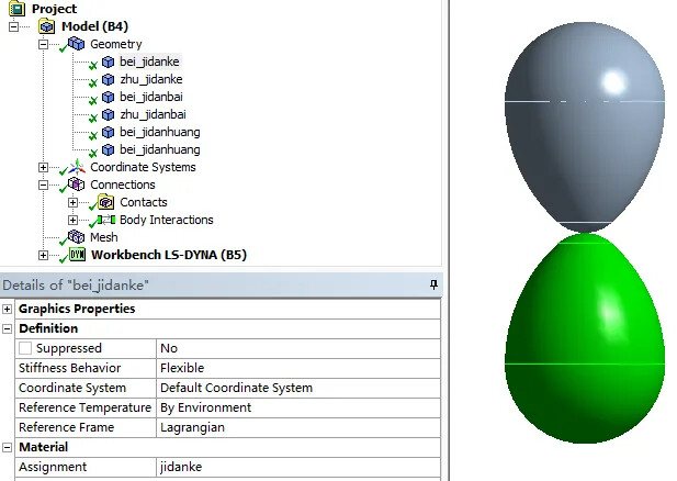
Double-click “Model” to enter the Mechanical interface. Expand “Geometry,” click on each geometric model, and select the corresponding material in the “Assignment” section of the list below. Keep the remaining settings as default.
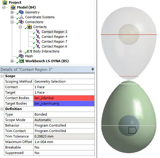
Expand “Contacts” and add 4 bonded contacts, corresponding to the two pairs: eggshell and egg white, egg white and egg yolk. Refer to the previous article: Common Constraint Types in Ansys Workbench for details. Keep the “Body Interactions” settings as default.
5. Set boundary conditions
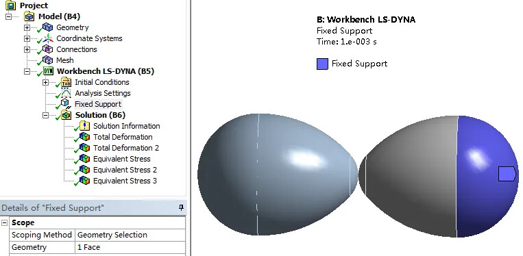
Set the right-side egg to be fixed. Right-click on “Workbench LS-DYNA,” add “Fixed Support,” and in the graphical interface, select the outer surface of the large end of the egg. Then, click “Apply” in the “Geometry” list below.
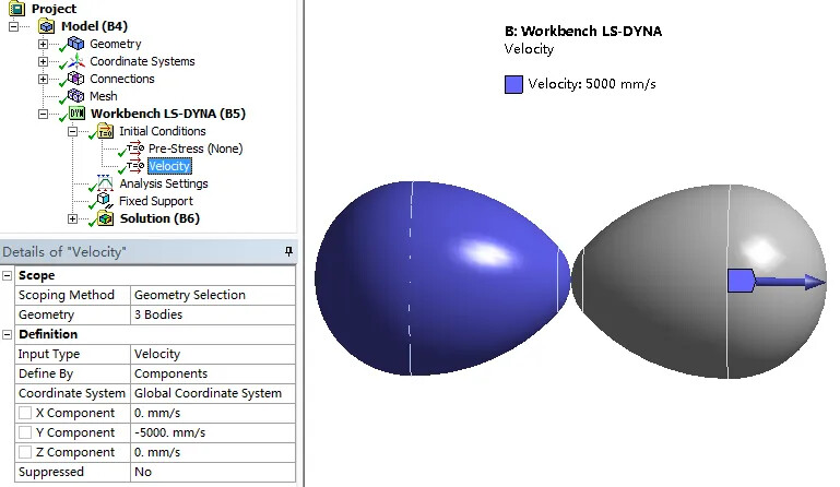
Set the left-side egg to collide with the right-side egg at a constant speed of 5 m/s. Right-click on “Initial Conditions,” add “Velocity,” and set it by components. In the graphical area, select the eggshell, egg white, and egg yolk, then click “Apply” in the list below.
6. Set up the solver
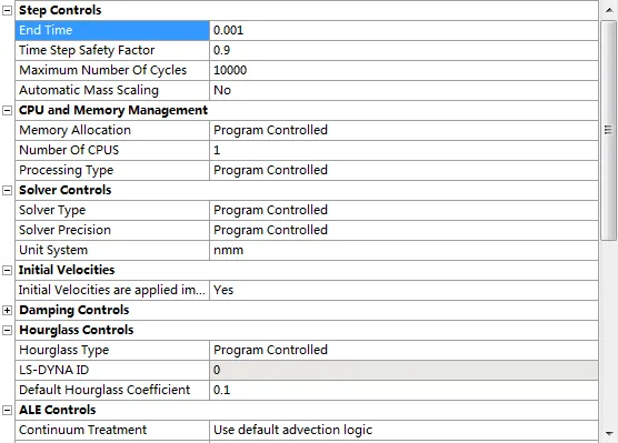
Click on “Analysis Settings,” and set the simulation time parameters in the list below: End time to 0.001s, Time Step Safety Factor to 0.9, and Maximum Number of Cycles to 10,000. Special note: It is important to set these parameters reasonably and adjust them gradually based on the solution results, as overly long solution times can occur!
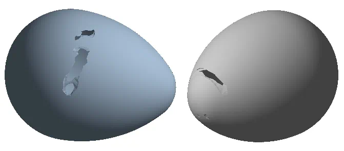
7.Post-processing of the solution results
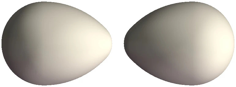
Right-click on “Solution,” and add “Total Deformation” and “Equivalent Stress.” Right-click on “Solution” again, select “Solve,” and perform the calculation. After completion, view and analyze the deformation and stress contour plots.
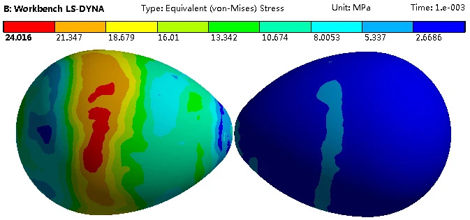
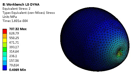
From the stress contour plots of the two eggs above, it can be observed that the maximum stress in the actively colliding egg on the left is 707.32 MPa, while the maximum stress in the egg being collided with on the right is 451.77 MPa. This indicates that the dynamic egg is more likely to fracture than the static egg!