Abstract A geometrical tolerance on a profile is one of the most versatile and powerful instruments that can be used for functional dimensioning, and is the tolerance most frequently used by designers. A profile may in fact be used to control the size, form, orientation and location of a feature. Because of the flexibility in the level of control that can be achieved with the profile tolerance, this control may be used to substitute the classical coordinate dimensioning method. The present chapter covers the ISO rules on profile tolerances in order to appropriately specify the control of a profile with a combination of the SZ, CZ, UF symbols and the bidirectional and unidirectional zones that are specified with profile tolerances. A composite profile tolerance is used in the ASME standards when the design applications require stricter tolerances on the form than is needed for the orientation or location of the same feature. The new ASME symbols, that is, From-To and dynamic profile, are presented.
10.1 Introduction
A geometrical tolerance on a profile is one of the most versatile and powerful instruments that can be used for functional dimensioning, in that it is not just a form tolerance, it also controls the size, orientation, position and, naturally, the form of a feature. A tolerance on a profile is usually only indicated on complex shaped features, but its use has spread over time to even simple profiles, in such a way that it has become the tolerance that is used the most frequently by designers.
The outline of a feature is defined as a profile; an outline defined on a drawing by theoretically exact dimensions is called a theoretical profile. The control of a profile specifies the limits, with respect to the theoretical profile, within which the elements of the surface must lie.
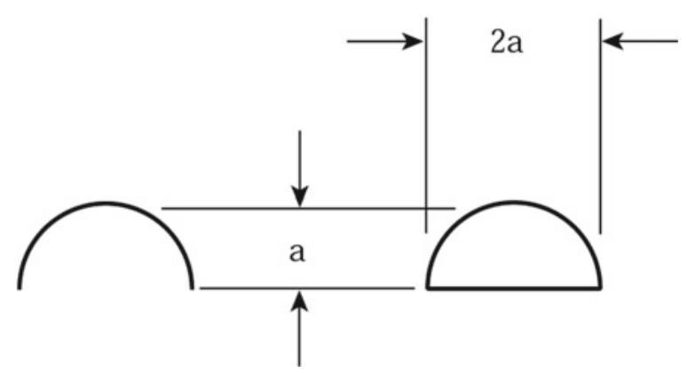
Fig. 10.1 Tolerance symbol on the profile of a line (on the left) and of a surface (on the right)
Two methods can be followed to indicate this type of geometrical error on a drawing:
(a) the first indicates the tolerance on the profile of a line, such as on an edge or any curve that defines a bi-dimensional tolerance zone; in this case, the symbol that should be placed within the tolerance frame is the one shown on the left in Fig. 10.1. A tolerance on a profile of a line is specified when an error on each feature of the surface becomes critical, and the variation from one feature to another becomes less important.
(b) The second method indicates the tolerance on the profile of a surface, in order to obtain the total control of a three-dimensional zone, sometimes with the use of one or more datum features; the symbol in the frame is similar to the previous one, but this time with a closed boundary (symbol on the right in Fig. 10.1).
A control of the profile may be used to substitute the classical coordinate dimensioning method, since tolerance profiles are no more restrictive than coordinate tolerances and are often equivalent. In fact, using a profile is similar to using coordinate tolerances with datums.
A plus/minus location dimension is used in the drawing in Fig. 10.2, since many engineers believe that it is very difficult to check a profile and this approach is more restrictive than coordinate tolerancing. In reality, from the metrologist’s point of view, the {90} \pm {0.2}\mathrm{\;{mm}} dimension inspection is a complicated procedure,since,according to ISO 14660-2:1999, the local size of two parallel extracted surfaces is the distance between two points on opposite extracted surfaces, where:
the connecting lines of sets of opposite points are perpendicular to the associated median plane; and
the associated median plane is the median plane of two associated parallel planes obtained from the extracted surfaces.
Furthermore, in this approach, the correct distance of the surface from datum A is not checked.
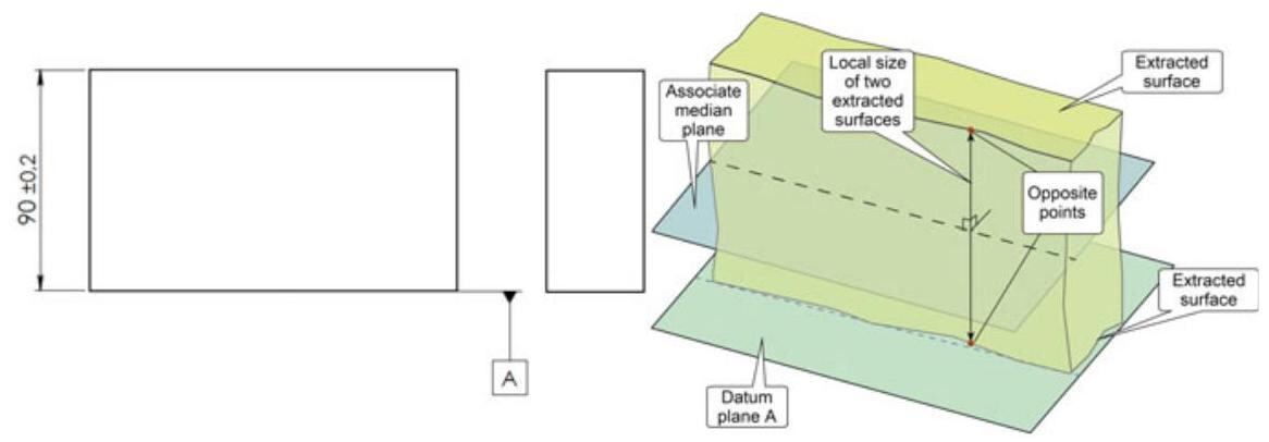
Fig. 10.2 From the metrologist’s point of view,the {90} \pm {0.2}\mathrm{\;{mm}} dimension inspection is a complicated procedure, since according to ISO 14660-2:1999, the local size of two parallel extracted surfaces is the distance between two points on opposite extracted surfaces, where the connecting lines of sets of opposite points are perpendicular to the associated median plane obtained from the extracted surfaces. Furthermore, in this way, the correct distance of the surface from datum A is not checked
Moreover,as can be seen in Fig. 10.3,the tolerance of \pm {0.2} on the height of the workpiece is substituted by the tolerance on the profile. The tolerance zone remains unvaried (±0.2) with respect to the theoretically exact size), but the profile control provides a clear definition of the tolerance zone, with uniform boundaries relative to a datum system. The location of the surface, as well as the parallelism, the flatness error and, naturally, the size are also controlled through the tolerance on the profile.
A profile tolerance is very easy to inspect by using a CMM, an optical comparator or a dial indicator, as shown in Fig. 10.4.
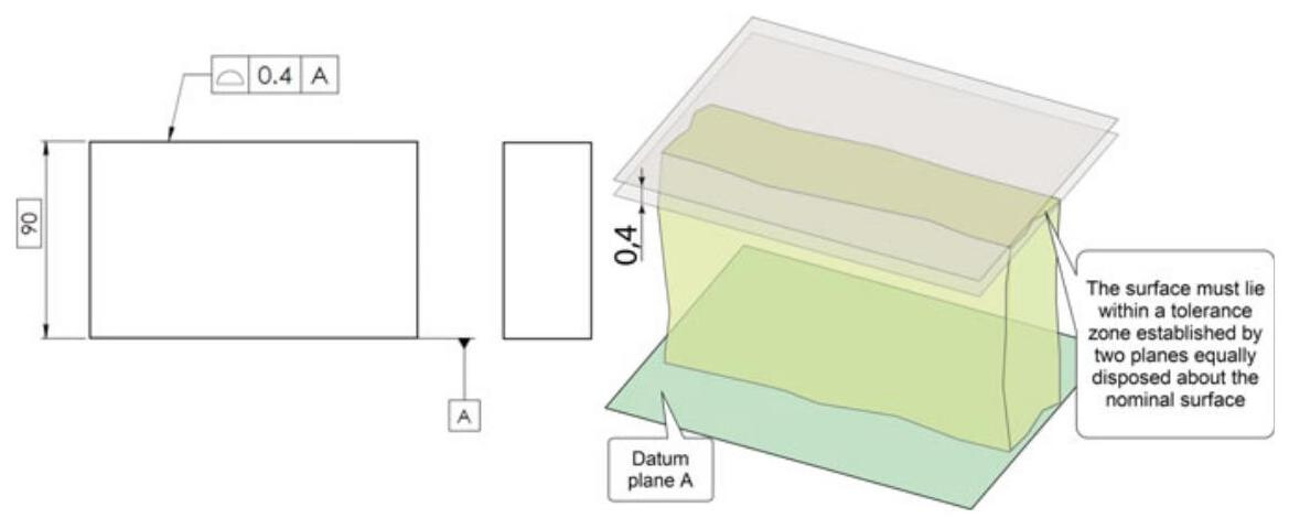
Fig. 10.3 Traditional dimensioning compared with dimensioning of the profile. The tolerance zone remains unvaried ( \pm {0.2} with respect to the theoretically correct size),but the profile control provides a clear definition of the tolerance zone
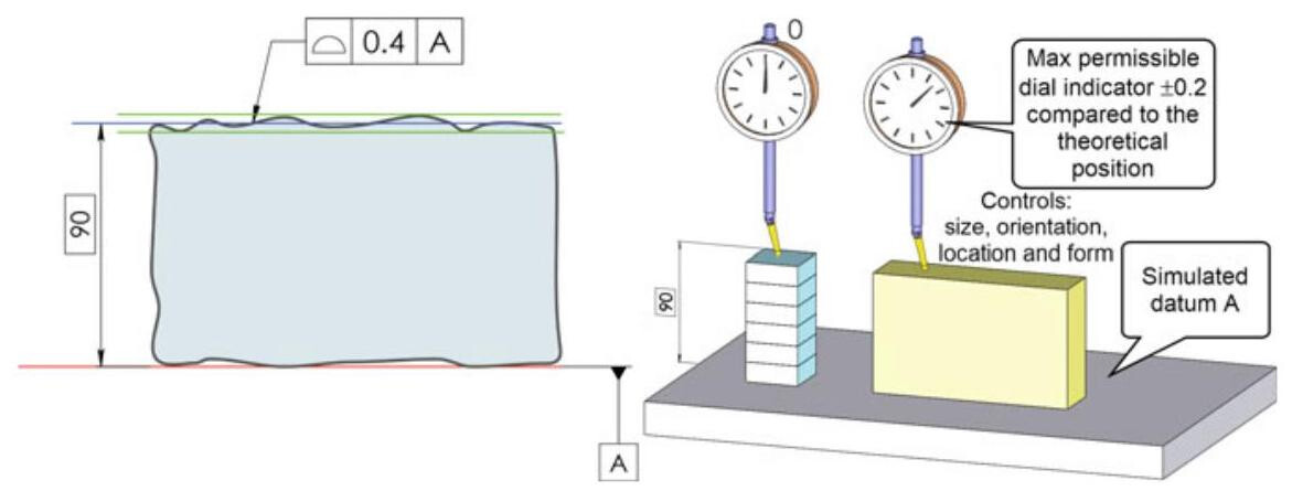
Fig. 10.4 A profile tolerance is very easy to inspect, and the location of the surface, as well as the size, the parallelism and the flatness error are controlled
10.2 Rules for Profile Tolerancing (ISO 1660:2017)
- When applying a profile tolerance, the theoretically exact feature (TEF) of the toleranced feature should be defined explicitly with theoretically exact dimensions (TEDs) or implicitly with the dimensions embedded in the CAD model.
- The tolerance zone for line profile specification is limited by two lines that envelope circles with a diameter equal to the tolerance value, the centres of which are situated on the TEF, unless otherwise specified (Fig. 10.5).
- The tolerance zone for surface profile specification is limited by two surfaces that envelope spheres with a diameter equal to the tolerance value, the centres of which are situated on the TEF (see Fig. 10.6), unless otherwise specified.
- According to the feature principle (ISO 8015, 5.4), by default a profile specification applies to one complete single feature.
- According to the independency principle (ISO 8015, 5.5), by default, a profile specification that applies to more than one single feature, applies to those features independently. If the profile specification has to apply to a united feature or a combined zone, the appropriate symbology should be specified (Fig. 10.7).
- The “all over” indication and the “all around” indication should always be combined with UF, CZ or SZ, when used for geometrical tolerancing, to make it explicit whether the specification applies to a united feature, defines a combined zone or defines a set of separate zones, except when all the non-redundant degrees of freedom for all the tolerance zones are locked by reference to datums.
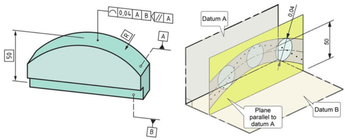
Fig. 10.5 The extracted profile line in each section, parallel to datum plane A, as specified by the intersection plane indicator, should fall between two equidistant lines that envelope 0.04 diameter circles, the centres of which are situated on a line which has the theoretically exact geometrical form with respect to datum plane A and datum plane B
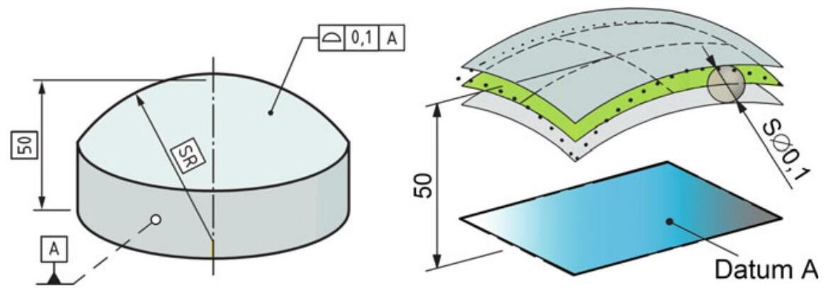
Fig. 10.6 The extracted surface should fall between two equidistant enveloping surfaces with a {0.1}\mathrm{\;{mm}} diameter sphere,the centres of which are situated on a surface that has the theoretically exact geometrical form with respect to datum plane A
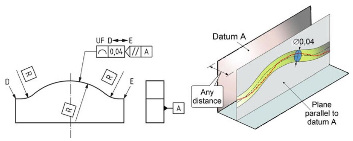
Fig. 10.7 Indication and interpretation of a line profile with an intersection plane indicator, using an intersection plane symbol. According to the independency principle, by default, a profile specification that applies to more than one single feature, applies to those features independently. In this case, it is necessary to use the UF (Unified Feature) symbol to indicate that the three circular sections are combined in one single feature
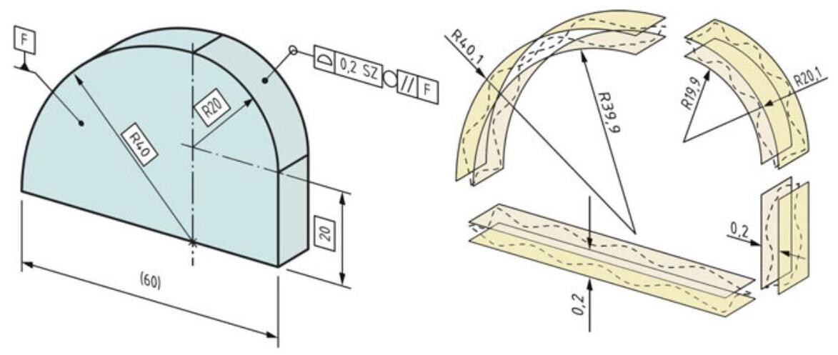
Fig. 10.8 Surface profile specification for a set of independent features
An example of the indication of a surface profile specification for a set of independent features is reported in Fig. 10.8 through the use of a collection plane symbol. To avoid ambiguity, the “all around” symbol is combined with the SZ specification element to indicate that the features are independent.
Since the “all around” symbol is used, the specification applies to a set of features that make up the periphery of the workpiece when seen in a plane parallel to datum F, as indicated by the collection plane indicator. The features are considered independent, and the meaning would be the same, if four leader lines were used to identify the four features.
The UF symbol in Fig. 10.9 indicates that the specification applies to a united feature. Since the “all around” symbol and the UF modifier are used, the specification applies to a united feature built from the features that make up the periphery of the workpiece when seen in a plane parallel to datum F ,as indicated by the collection plane indicator. The meaning would have been the same, if four leader lines had been used to identify the four features instead of the “all around” symbol. The specification does not reference datums, and the tolerance zone is therefore not constrained.
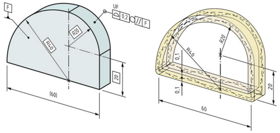
Fig. 10.9 Surface profile specification for a united feature. Since the periphery is considered one feature, the spheres that define the limits of the tolerance zone are rolled across the discontinuities in the feature to create round corners in the tolerance zone on the outside of the discontinuities
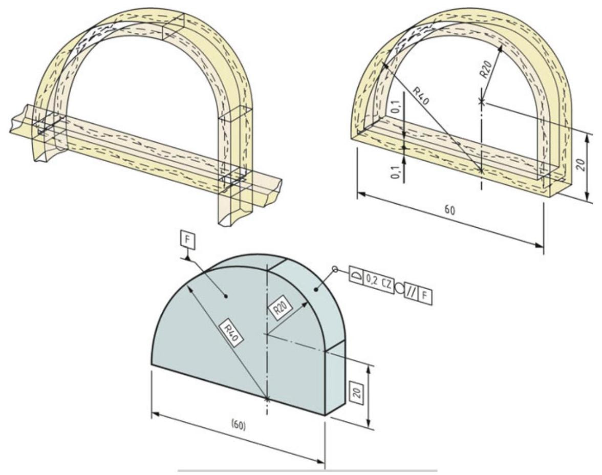
Fig. 10.10 Combined surface profile specification for a set of features. The illustration shows the four zones and how the zones are combined so that the part has sharp outside corners
The drawing indications in Fig. 10.10 differ from those in Fig. 10.9 in that the CZ modifier is used instead of the UF modifier to indicate that the specification is a combined tolerance zone that applies to a set of features. Since the “all around” symbol is used, the specification applies to a set of features that make up the periphery of the workpiece, when seen in a plane parallel to datum F, as indicated by the collection plane indicator.
10.3 Profile Interpretation
A tolerance on a profile of a surface can be used to control:
- only the size and form of a profile (the profile control is specified without any datum references, Fig. 10.11a);
- the size, form and the orientation, through the use of one or more datums (Fig. 10.11b)
- the size, form, orientation and position at the same time (Fig. 10.11c). Because all the non-redundant degrees of freedom for the tolerance zone are locked by means of reference to a datum system, the UF modifier could be omitted without changing the practical meaning of the specification. In this case, the tolerance zone is completely constrained by the datum system.
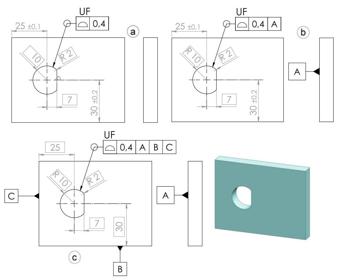
Fig. 10.11 Control of the size and form (a), the size, form and orientation (b) and the size, form, orientation and position (c). In this case, because all the non-redundant degrees of freedom for the tolerance zone are locked by means of reference to a datum system, the UF modifier could have been omitted without changing the practical meaning of the specification
10.4 Offset Tolerance Zone Specification
By default, the tolerance zone is symmetrical with respect to the ideal profile, but it is also possible to indicate a non-symmetrical zone through the use of modifiers (Fig. 10.12). In fact, the ISO 1101 standard has introduced the UZ modifier, with which the number after this symbol represents the deviation required by the nominal, and it can therefore be either negative (within the ideal profile) or positive (external).
In practice, the extracted surface should fall between two equidistant enveloping surface spheres of a defined diameter that is equal to the tolerance value, the centres of which are situated on a surface that corresponds to the envelope of a sphere in contact with the theoretically exact feature (TEF) and whose diameter is equal to the absolute value given after UZ, with the direction of the offset indicated by a sign, where the “+” sign indicates “outside the material” and the “-” sign indicates “inside the material” (Fig. 10.13, the position of this sphere depends on whether the sign is positive or negative). The offset sign should always be indicated.
The UZ modifier in Fig. 10.14 is used to control a surface location with the position symbol. This combination can only be used for planar features.
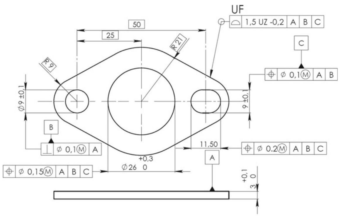
Fig. 10.12 Use of the UZ symbol to specify a tolerance on a non-symmetrical profile. The UF modifier could be omitted
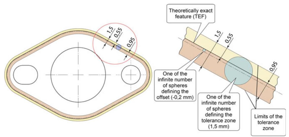
Fig. 10.13 Offset tolerance zone with the specified offset
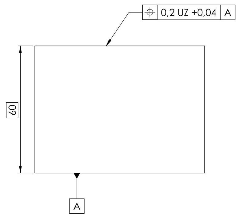
Fig. 10.14 The UZ specification modifier can only be used in combination with the position symbol for planar features
10.5 Constraint Specification Elements
10.5.1 Offset Tolerance Zone with an Unspecified Linear Offset
Another interesting constraint pertaining to the tolerance of a profile, which was introduced with the ISO 1101 standard of 2017, is the OZ symbol (which should not be confused with the previous UZ symbol). The OZ symbol has the objective of indicating a tolerance zone that is offset by a constant but unspecified amount. The theoretically exact feature (TEF) of the toleranced feature should usually be defined with theoretically exact dimensions (TEDs) in the specification of a profile control, as in Fig. 10.15a. In the case of the sphere in Fig. 10.15b, the specification of the profile control is ambiguous, since the nominal size of the TEF is not defined by a TED, and there is only a $ \pm $tolerance indicated for the size. In this case, the specification element OZ should always be indicated for profile specifications to make it explicit that the size of the TEF is not fixed. In short, if the shape of the TEF is defined, but the nominal linear size of the TEF is undefined, the OZ modifier should always be indicated.
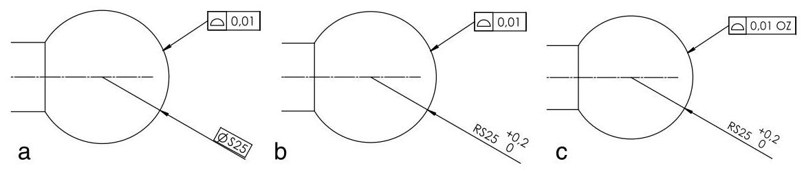
Fig. 10.15 Profile control on a spherical surface. The TEF of the toleranced feature should be defined with TEDs (a). The specification in (b) is ambiguous, since the nominal size of the TEF is not defined by a TED and there is only a \pm tolerance indicated for the size. In this case,the specification element OZ should always be indicated (c)
Since there are no bounds on the offset, a specification with the modifier is usually combined with a specification using a larger tolerance without a modifier, as in Fig. 10.16. When both specifications are satisfied, this combination controls the shape of the tolerance feature within the larger, fixed tolerance zone.
The non-redundant degrees of freedom for the tolerance zone defined by the upper tolerance indicator are locked by means of reference to a datum system, and the UF modifier could therefore have been omitted. In the case of the tolerance zone defined by the lower tolerance indicator, the UF modifier is necessary to synchronise the offset of the two parts of the tolerance zone.
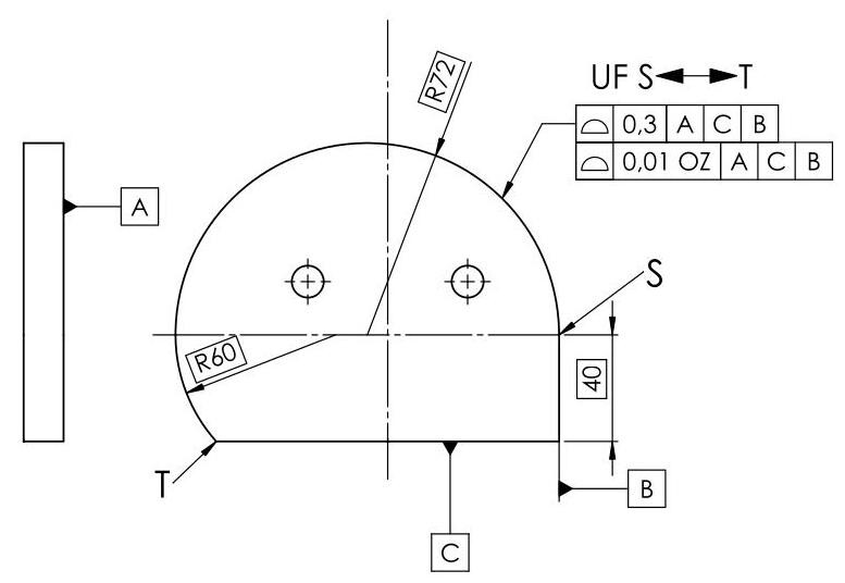
Fig. 10.16 Combination of a fixed and an off-set specification
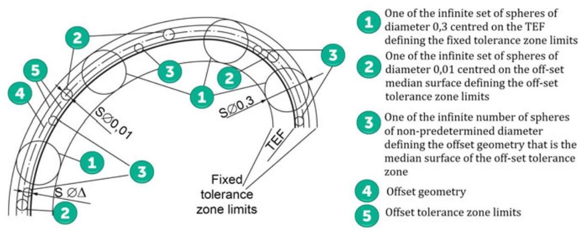
Fig. 10.17 Interpretation of the tolerance zones
Figure 10.17 shows the interpretation of the drawing in Fig. 10.16, where a combination of a fixed tolerance zone with a larger tolerance value (0.3) and an off-set tolerance zone with a smaller tolerance value (0.01) are defined. The off-set tolerance zone is off-set by a non-predetermined amount, either inside the material or outside the material, compared to the TEF. The combination of the two specifications controls the shape of the toleranced feature within the off-set tolerance zone, which can adapt to the toleranced feature, as long as the off-set tolerance zone remains within the fixed tolerance zone.
10.5.2 Offset Tolerance Zone with an Unspecified Angular Offset
In the case of a feature of angular size, as in Fig. 10.18, a profile specification of a cone surface is indicated with its size considered as fixed, while the angle of the cone is indicated with a theoretically exact dimension (TED). Therefore, the extracted surface of the cone is required to be inside the tolerance zone, without any orientation or location constraints, according to ISO 3040:2016. The tolerance zone consists of the space between two coaxial conical surfaces {0.3}\mathrm{\;{mm}} apart,with a specified theoretical angle. However, when a tolerance zone does not take the nominal size into account, the VA modifier (variable angular size) should be indicated.
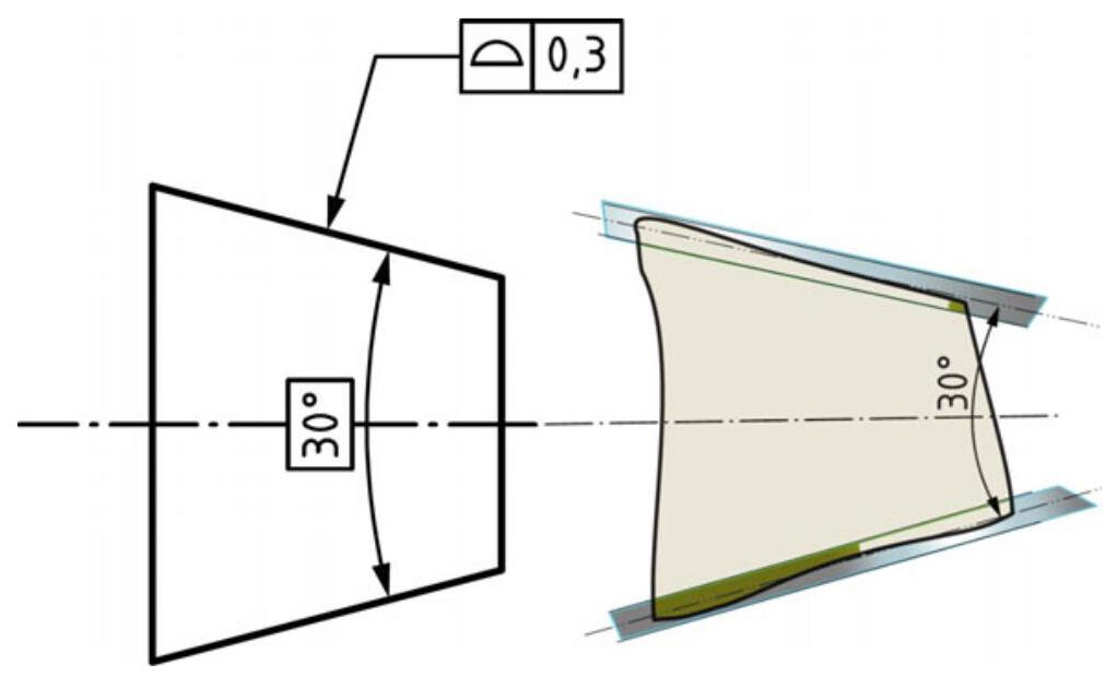
Fig. 10.18 Indication of a profile specification of a cone surface with its size considered as fixed
When a nominal angular size of the TEF is not defined by a TED for cones, e.g. in the case where there is only a \pm tolerance indicated for the angular size,the VA specification element should always be indicated for profile specifications to clearly indicate that the angular size of the TEF is not fixed. The extracted surface of the cone in Fig. 10.19 is required to be inside the tolerance zone, without any orientation or location constraints. The tolerance zone consists of the space between two coaxial conical surfaces {0.3}\mathrm{\;{mm}} apart,with the same unspecified angle. The local angles are required to fall between the lower and upper tolerances.
Since there are no bounds on the angular offset, a specification with the VA modifier is usually combined with another specification such as an angular dimensional specification or geometrical specification, without any VA modifier, as in Figs. 10.19 and 10.20.
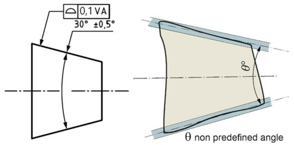
Fig. 10.19 Indication of a profile specification of a cone surface with its size considered as variable
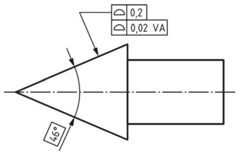
Fig. 10.20 Combination of a fixed and a variable angle specification
10.6 Pattern Specification (ISO 5458:2018)
The ISO 5458:2018 standard establishes rules that are complementary to ISO 1101, which should be applied to pattern specifications, and defines rules to combine individual specifications for the control of profiles. Figure 10.21 provides an example which illustrate the internal constraints introduced by the CZ or CZR modifiers and the external constraints introduced by a datum or datum system. Figure 10.22 shows the interpretation of each tolerance indicator. The CZ modifier indicates that a tolerance zone pattern is defined with internal orientation and location constraints between the individual tolerance zones. The CZR modifier indicates that a tolerance zone pattern is defined with internal orientation constraints between the individual tolerance zones.
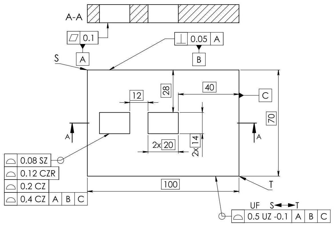
Fig. 10.21 Examples of the internal constraints introduced by the CZ and CZR modifiers and the external constraints introduced by the datum system
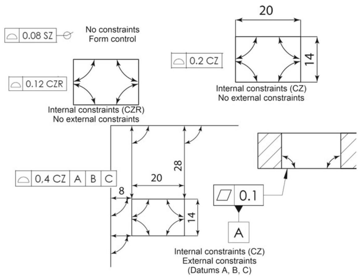
Fig. 10.22 Interpretation of the internal constraints introduced by the CZ or CZR modifiers and the external constraints introduced by a datum or datum system
The specifications in Fig. 10.23 are two pattern specifications (CZ in the SZ CZ sequence) considered independently (first SZ in the sequence). The toleranced feature of each pattern specification is the collection of four extracted integral surfaces (all around symbol), and the tolerance zone pattern is composed of four tolerances zones, constrained to each other in orientation (implicit TEDs {0}^{ \circ } and {90}^{ \circ } ) and in location to be {20}\mathrm{\;{mm}} (in one direction) and {14}\mathrm{\;{mm}} (in another perpendicular direction) apart, with explicit TEDs, without any external constraint from a datum system. The two tolerance zone patterns are independent of each other, i.e. they are free to move and rotate in relation to each other.
The specification in Fig. 10.24 is a pattern specification (first CZ in the CZ CZ sequence) defined by two \left( {2 \times }\right) tolerance zone patterns (last CZ in the sequence).
Here, there are two (2x) pattern specifications (last CZ) which are dependent on each other (first CZ), thereby creating a global pattern specification. The toleranced feature is the collection of eight extracted integral surfaces ( 2 \times and the all around symbol).
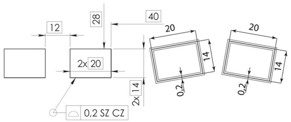
Fig. 10.23 Two pattern specifications (CZ in the SZ CZ sequence) considered independently (first SZ in the sequence). The two tolerance zone patterns are free to move and rotate in relation to each other
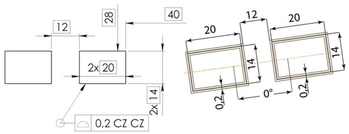
Fig. 10.24 The specification is a pattern specification (first CZ in the CZ CZ sequence) defined by two (2x) tolerance zone patterns (last CZ in the sequence)
The tolerance zone is a tolerance zone pattern consisting of two tolerance zone patterns (CZ CZ), composed of four tolerance zones, in a space between two parallel planes {0.2}\mathrm{\;{mm}} apart and constrained in orientation (implicit TEDs 4 \times {90}^{ \circ } ) and in location (explicit TEDs 20 × 14). The two tolerance zone patterns are constrained in orientation to be parallel (implicit TED of {0}^{ \circ } ) and in location to be {12}\mathrm{\;{mm}} apart in one direction (explicit TED) and aligned (implicit TED of 0\mathrm{\;{mm}} apart) in the perpendicular direction, without any external constraint from a datum.
NOTE: The last CZ modifier in the CZ CZ sequence creates a tolerance zone pattern composed of four tolerance zones. The first CZ in the CZ CZ sequence creates the dependency between the two tolerance zone patterns.
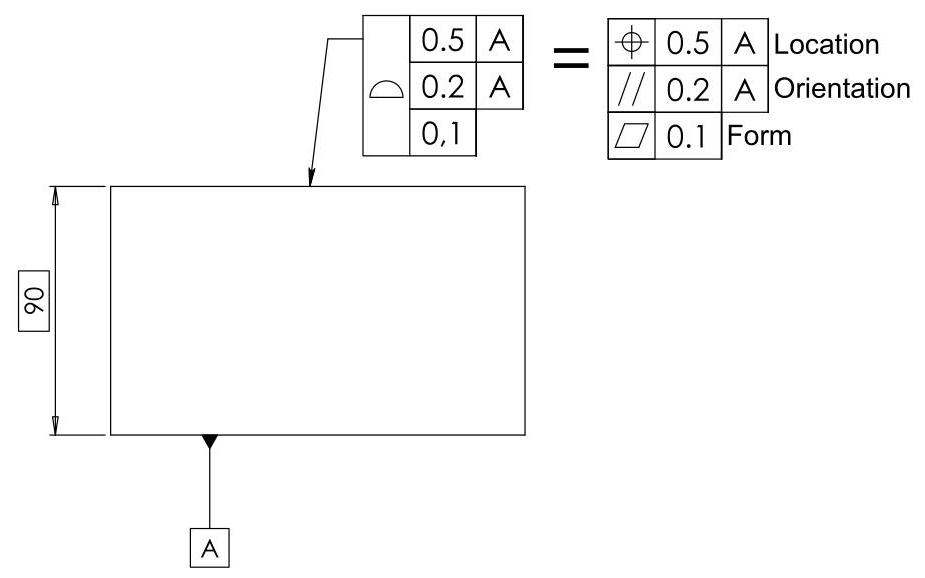
Fig. 10.25 Use of a tolerance on a composite profile. The first uppermost frame controls the position of the surfaces, while the second frame is used for the orientation tolerance. The form tolerance (flatness) and the size are defined by adding a third frame (without adding a datum)
10.7 The Tolerance of a Profile in the ASME Standards
10.7.1 Composite Profile Tolerancing
The ASME Y14.5 standard also foresees the use of composite profile tolerancing for profiles (this is not foreseen in the ISO standards and it is also used for location tolerances), a fact which determines a multiple control of the geometric profile, where the design requirements are such that the tolerance for the location of a part feature is less important than the orientation of the feature (Fig. 10.25). The upper segment of a composite profile feature control frame controls the location of the surface, while the second frame is used to control the orientation of a toleranced feature relative to datum A (from necessity, the value must be smaller). By adding a third segment (without adding a datum), a form tolerance is defined (a flatness tolerance, in this case) and the size is also controlled.
In short, in many cases, it becomes more important to control the form and the orientation of a profile than its position, as in the case of the workpiece shown in Fig. 10.26.
10.7.2 Unilateral and Unequally Disposed Profile Tolerance
In order to indicate a tolerance on a non-symmetrical profile, the ASME Y14.5 standard of 2009 introduced the modifier (C) (unequally disposed profile symbol) to indicate a unilateral and unequally disposed profile with respect to a theoretically exact profile, as shown in Fig. 10.27. The (c) symbol is placed in the feature control frame after the tolerance value. The value after the symbol indicates the entity of the profile tolerance in the direction that would allow additional material to be added to the true profile (if the number is zero, the error is completely inside the profile).
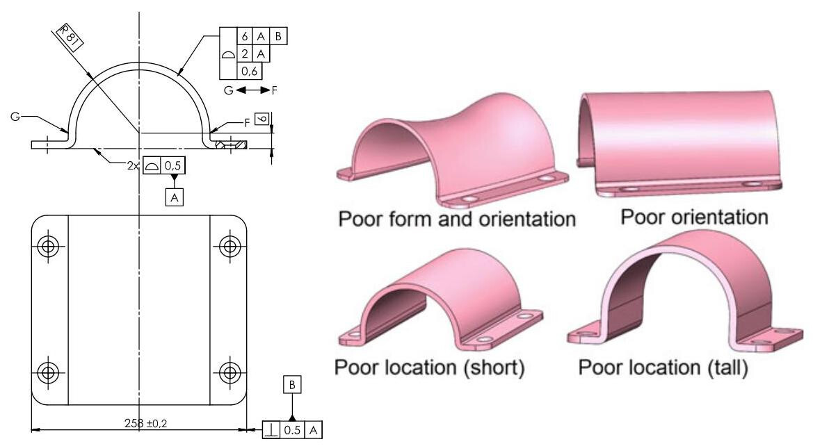
Fig. 10.26 The use of composite profile tolerancing allows the position of a surface to be controlled with a rather large error (first frame, 6\mathrm{\;{mm}} ) and,at the same time,a more rigorous control of the orientation \left( {2\mathrm{\;{mm}}}\right) ,form and size \left( {{0.6}\mathrm{\;{mm}}}\right) to be obtained
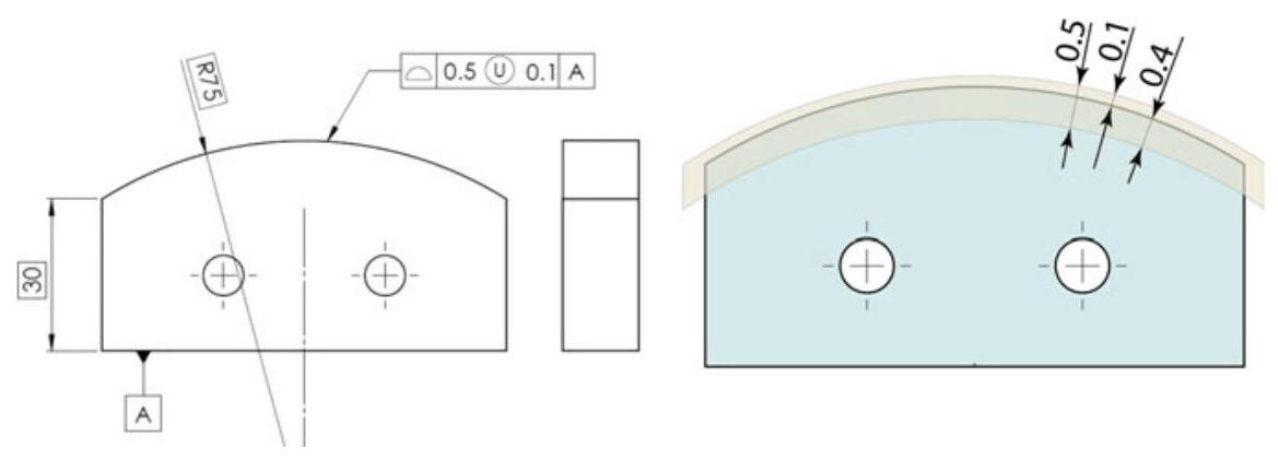
Fig. 10.27 The (C) modifier indicates an unequally disposed profile with respect to a theoretically exact profile. The value after the modifier indicates the entity of the tolerance in the direction that would allow additional material to be obtained
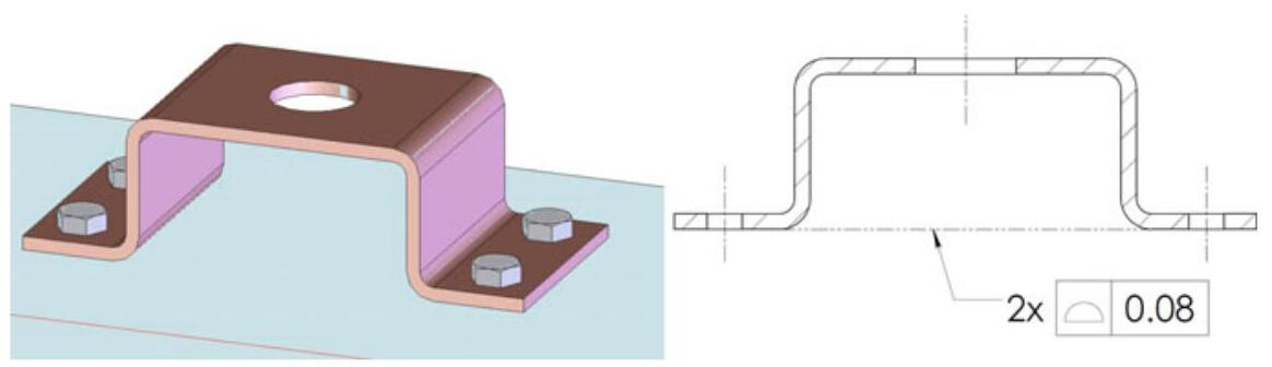
Fig. 10.28 In the ASME standard, a profile of a surface may be used to control the mutual orientation and location of two or more surfaces
10.7.3 Coplanarity
Coplanarity is the condition of two or more surfaces having all the elements on one plane. When it is important to treat two or more surfaces as a single continuous one, (a coplanar one, for example), the ISO standards use the CZ (Combined Zone) symbol. In the ASME standard, a profile of a surface tolerance may be used to control the mutual orientation and location of two or more surfaces, as shown in Fig. 10.28. The profile of a surface tolerance establishes two tolerance zones, parallel to each other with zero offset, within which the considered surfaces should lie.
10.7.4 The New Symbols (ASME Y14.5:2018)
The function of the dynamic profile is to allow form to be controlled independently of size. It is a small triangular symbol \Delta that can be inserted inside the feature control frame of a profile control (after the tolerance value, as in Fig. 10.29). The tolerance of the profile is usually applied to the theoretical or ideal profile (indicated with basic dimensions), for which the shape and size are checked: through the use of the dynamic profile modifier, the error of form is defined independently of the size.
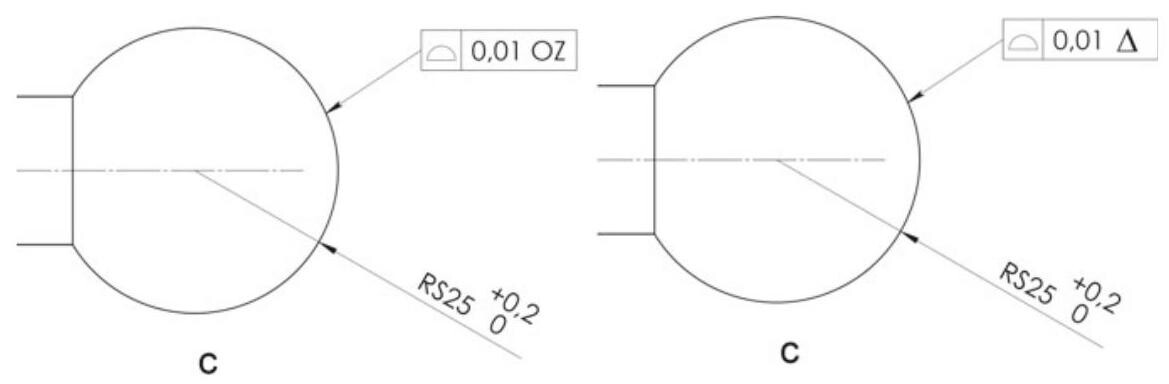
Fig. 10.29 The function of the dynamic profile is to allow form to be controlled independently of size. The concept of dynamic profile corresponds to the OZ (Unspecified linear tolerance zone offset) symbol of the ISO 1101 standard
For example, let us suppose that the spherical end of a pin should be controlled by the profile of a surface. Without the dynamic profile modifier, the diameter of the sphere should be indicated with a basic dimension, because the control must be applied to an “ideal profile”. With this new modifier, the diameter of the sphere can still have its dimensional tolerance \pm ,but with a smaller dynamic profile value to control the shape.
When the dynamic tolerance modifier is applied to a lower segment of a composite tolerance without any datum feature references, the tolerance zone controls the form but not the size of the feature and it uniformly progresses (expands or contracts) normal to the true profile while maintaining the specified constant width, as in Fig. 10.30. The 0.5 profile tolerance zone is constrained in translation and rotation relative to the datum reference frame established by datum features A, B, and C. The 0.1 dynamic profile is free to translate, rotate and uniformly progress (expand or contract) and the actual feature should simultaneously be within both tolerance zones.
The new ASME Y14.5:2018 From-To symbol indicates a specification transition from one location to another location to define a non-uniform profile tolerance zone. The “from” and “to” locations may be points, lines, or even features, and the leader from the feature control frame should be directed towards the portion of the feature to which that tolerance applies.
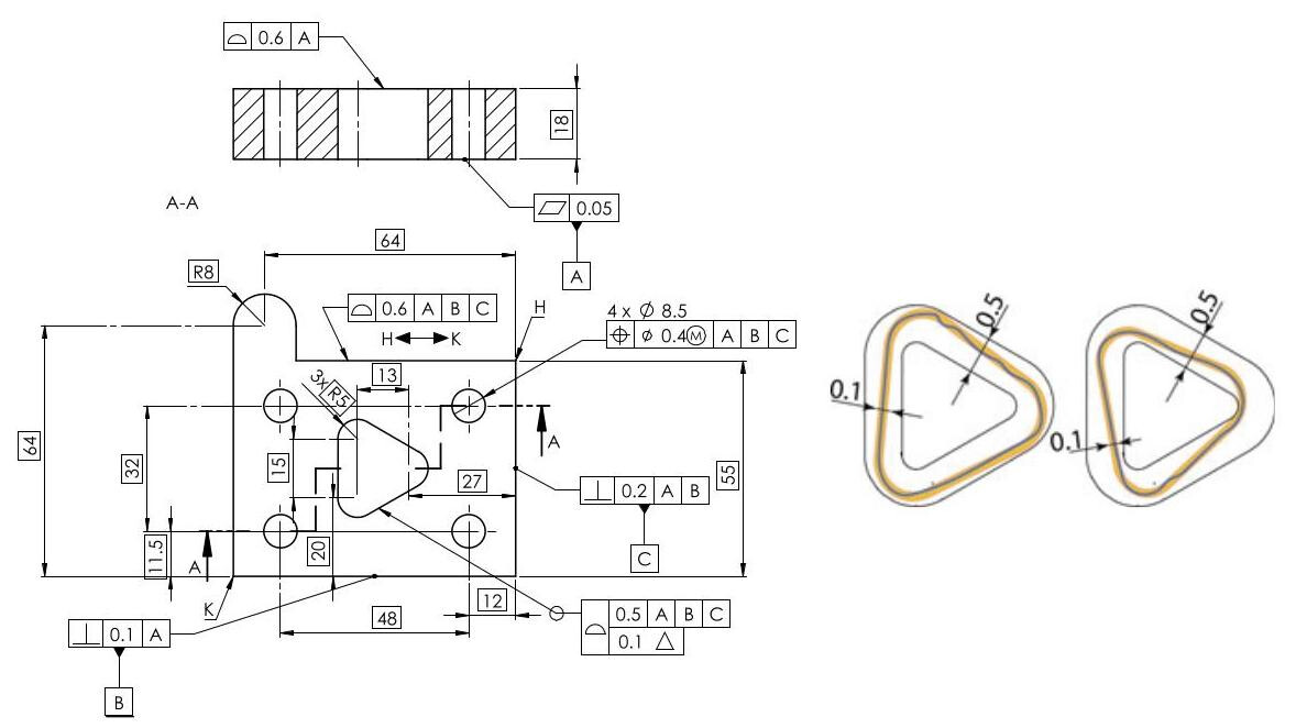
Fig. 10.30 Composite profile with a dynamic profile to control form. The 0.1 dynamic profile is free to translate, rotate and uniformly progress (expand or contract) and the feature should be located within the {0.5}\mathrm{\;{mm}} tolerance zone
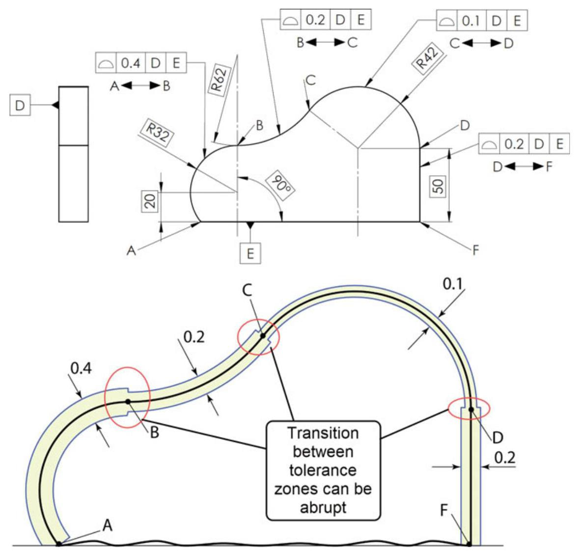
Fig. 10.31 Non-uniform profile tolerance zone with three abrupt tolerance transitions that occur at points B, C, and D, when different profile tolerances are specified
Figure 10.31 shows three abrupt tolerance transitions that occur at points B, C, and D, when different profile tolerances are specified on adjoining segments of a feature. In order to avoid this problem, the From-To symbol is used to smooth the transition areas, as in Fig. 10.32.
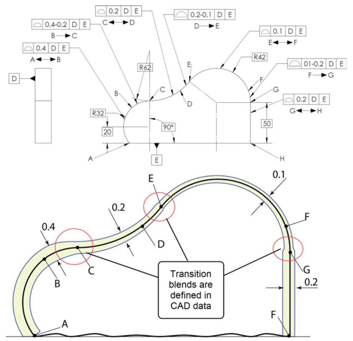
Fig. 10.32 The From-To symbol is used to smooth the transition areas