Abstract It is possible to control four form tolerance types: straightness, flatness, roundness and cylindricity. The chapter covers all the concepts necessary to define specification operators (according to ISO 17450-2) and some procedures to establish the reference elements in order to define the deviation errors. Some terms related to form parameters are described such as peak-to-valley, peak-to-reference and reference-to-valley deviations. The ASME standards use the envelope requirements or Rule #1, according to which form tolerances are contained within the dimensional ones, and these tolerances are therefore only used with the purpose of limiting the error when the workpiece is produced with dimensions close to the least material condition.
7.1 Introduction
Form tolerances are used to establish the variation limits of a surface or of a feature of the ideal form indicated on a drawing; in short, the form error of a feature is limited with respect to its perfect and ideal counterpart (plane, line or circle).
It is possible to control four types of form tolerance: straightness, flatness, roundness and cylindricity. The ASME standards use the envelope requirements or Rule #1, according to which form tolerances are covered by the dimensional ones, and these tolerances are therefore only used when necessary.
Since, as already mentioned, a profile tolerance controls not only form errors, but also size, location and orientation errors, a specific section is dedicated to this topic.
7.2 Straightness Tolerance
Straightness is the condition in which a linear feature (or any linear feature of a surface) results to be perfectly straight. Straightness is basically a characteristic of a line, such as an axis or an edge of a feature; however, this type of tolerance can also be applied to flat, cylindrical or conic surfaces, which are considered to be composed of an infinite number of longitudinal features.
A straightness symbol should obviously be placed in the drawing view where the feature explicitly appears straight. Figure 7.1 indicates the interpretation of a straightness tolerance of 0.03mm placed on a cylindrical surface: each longitudinal line element of the cylinder should be between two parallel lines at a distance of 0.03 , on a plane composed of the axis and the two lines themselves. A tolerance zone is bi-dimensional, and one of the two lines of the tolerance zone is orientated by the extreme points of the line element of a surface, while the other line is parallel to the first and distanced by the tolerance.
Three possible types of error are visible on the cylindrical surface shown in the same figure, that is, of concavity, convexity and of bending. A straightness tolerance applied to a flat surface only controls the straightness in the direction parallel to the projection plane.
In the case shown in Fig. 7.2, the straightness tolerance is limited by two parallel lines 0.1mm apart,in the direction specified by the plane intersection symbol (or, in the case in which a symbol is missing, in the direction parallel to the projection plane). The tolerance zone is therefore limited by two parallel lines at a distance specified by tolerance t, at any intersection plane parallel to datum A (Fig. 7.3).
Figure 7.4 shows the application of a straightness tolerance of the surface of a shaft (integral feature). As the principle of independence comes into force by default, the following rules are valid :
(1) A tolerance zone is applied to each line element individually.
(2) The maximum virtual boundary is obtained by summing the maximum material size and the straightness tolerance.
(3) The straightness tolerance may be larger than the size tolerance.
(4) Each local size should fall within the size tolerance limits.
In the case of the application of the envelope requirement (circled E symbol), the straightness must be perfect when the component is produced at the maximum material condition (Fig. 7.5) and the geometrical tolerance should always be less than the size tolerance. It should be recalled that this case represents the default conditions in the ASME standards.
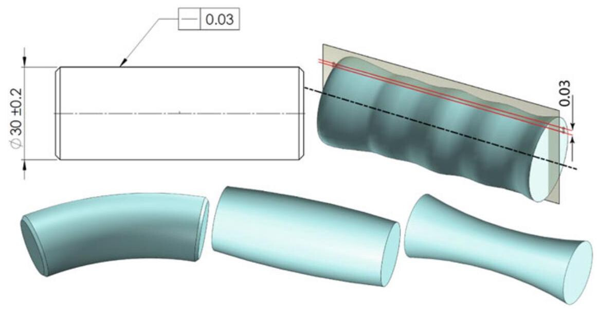
Fig. 7.1 Interpretation of a straightness tolerance of 0.03 placed on a cylindrical surface: each line element of the cylinder should be between two parallel lines 0.03 apart, in a plane composed of the axis and the two lines themselves
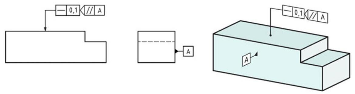
Fig. 7.2 Straightness tolerance applied to a flat surface: the direction is specified by the plane intersection symbol
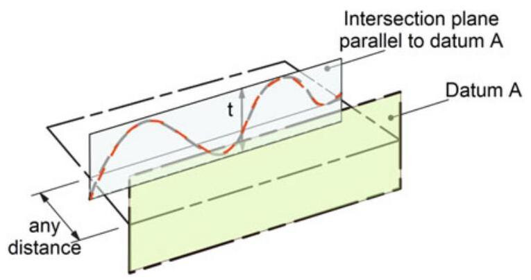
Fig. 7.3 Interpretation of the tolerance zone shown in Fig. 7.2. The tolerance zone is limited by two parallel lines at a distance specified by tolerance t, in any intersection plane parallel to datum A
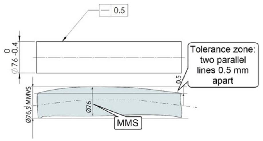
Fig. 7.4 Application of a straightness tolerance to the surface of a shaft. As the principle of independency comes into force by default, the maximum virtual boundary is obtained by summing the maximum material size with the straightness tolerance, which can be greater than the size tolerance
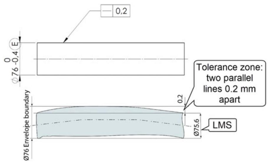
Fig. 7.5 In the case of the envelope requirement being applied (circled symbol E next to the diameter value), the straightness must be perfect when the component is produced at the maximum material and the geometrical tolerance should always be less than the size tolerance
7.2.1 Straightness Parameters
The ISO 12780 standard explains the terms and concepts necessary to define specification operators (according to ISO 17450-2) for the straightness of integral features.
According to this standard, the extracted straightness line is a digital representation of the intersection of the real surface and a straightness plane, which includes the normal of the real surface (Fig. 7.6). The straightness profile is an extracted line intentionally modified by a filter. In the evaluation of a straightness deviation of an integral feature with a given tolerance, the straightness profile should be contained between two lines that are distant from each other by a value that is less than or equal to the specified tolerance value.
When determining the orientation of the tolerance zone, it is necessary to establish a reference line, that is, an associated line that fits the straightness profile according to specified conventions, and to which the deviations from straightness and the straightness parameters refer. The ISO 12780-1 technical specification considers two procedures for the determination of the reference line:
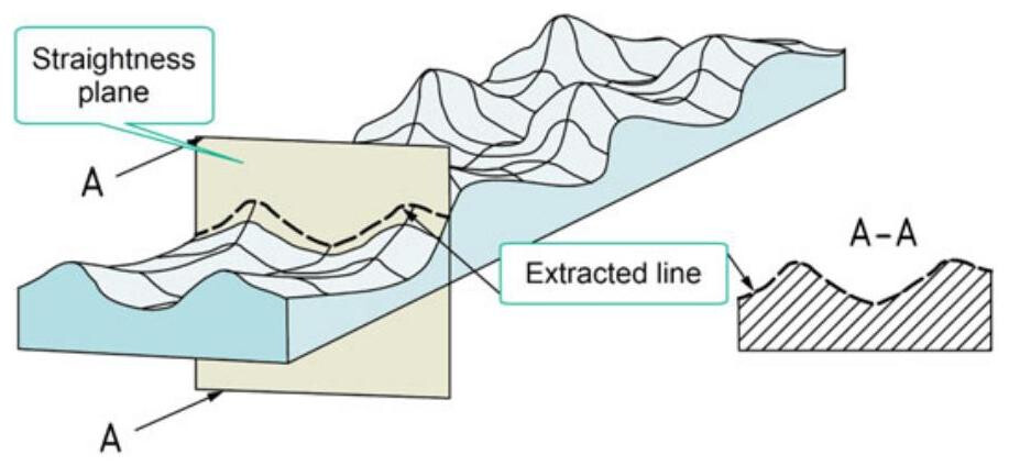
Fig. 7.6 The extracted straightness line is a digital representation of the intersection of the real surface and a straightness plane, normal to a real integral surface
- The minimum zone reference line method (MZ), which best satisfies the tolerance zone definition (Fig. 7.7).
- The least squares reference line method (LS), which provides a good approximation of the straightness deviation, although overestimating it, and is currently the most frequently used in coordinate measuring machines.
The local straightness deviation is defined as the deviation of a point on a straightness profile from the reference line, in the direction normal to the reference line.
Some terms related to straightness parameters are listed hereafter:
(1) Peak-to-valley straightness deviation, which is the value of the largest positive local straightness deviation added to the absolute value of the largest negative local straightness deviation. The GT modifier is used in specifications to indicate that a form tolerance applies to the peak-to-valley deviation relative to the least squares reference element.
(2) Peak-to-reference straightness deviation, which is the value of the largest positive local straightness deviation from the least squares reference line.
(3) Reference-to-valley straightness deviation, which is the absolute value of the largest negative local straightness deviation from the least squares reference line.
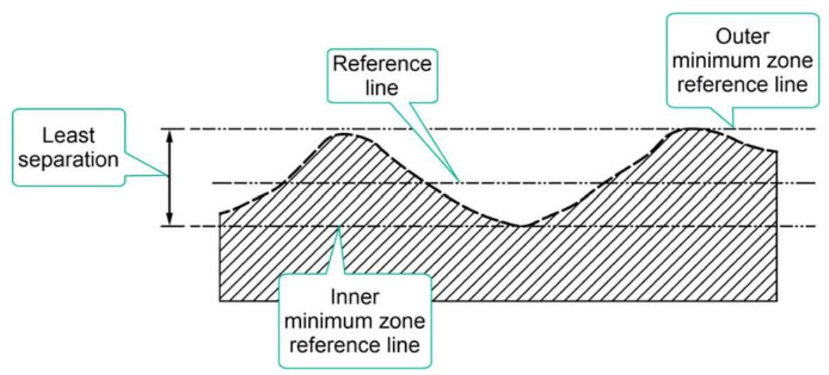
Fig. 7.7 Minimum zone reference line
Table 7.1 Deviation parameters. The peak height and the valley depth are only defined relative to the minimax (Chebyshev) association and the least squares (Gaussian) association
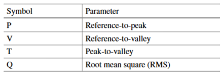
The Table 7.1 shows the parameter specification elements that can be used for form specifications, i.e. specifications that do not reference datums. T may be used to indicate the total range of deviations, i.e. the default parameter. P, V should be used to indicate the peak height, and the valley depth, respectively. Q should be used to indicate the square root of the sum of the squares.
7.2.2 Straightness Tolerance Applied to a Feature of Size
Let us now examine the case in which the straightness tolerance is applied to a feature of size, that is, to a derived median line; in this case, the tolerance has been indicated on the dimension that expresses the diameter, and reference is therefore made to the median line which must remain within a three-dimensional tolerance area, limited by a cylinder with the same diameter as the tolerance itself, and this is indicated by placing the diameter symbol \phi before the number that expresses the tolerance value (Fig. 7.8). In this case, the straightness tolerance can be greater than the size tolerance of the diameter of the associated cylinder.
Figure 7.9 shows, for the case of a shaft, the concept of derived median line, obtained by means of a set of central points of the single sections. In practice, a cylinder, from which the axis is derived, is associated with the extracted surface (e.g. utilising a Gaussian interpolation). A line, to which a Gaussian circle is associated, and whose centre determines a point of the derived median line, is extracted from each section perpendicular to the axis.
When a geometrical control is applied to a feature of size, it is possible to use the maximum material requirement (MMR), with the advantages that are derived from the increase in the tolerances, as can be seen in Fig. 7.10. The combined effect of the size error and the straightness error generates a virtual size (MMVS), which represents the worst possible mating condition.
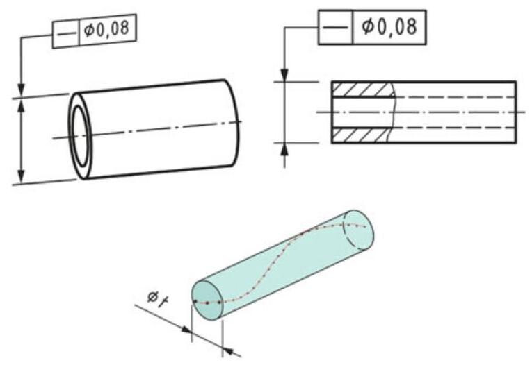
Fig. 7.8 A straightness tolerance is applied to a feature of size; in this case, the tolerance is indicated on the dimension that expresses the diameter, and reference is therefore made to the extracted median line of the cylinder; the tolerance zone is three-dimensional and limited by a cylinder with a diameter equal to the tolerance itself
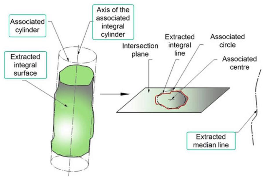
Fig. 7.9 The extracted median line obtained from a set of central points of the single sections perpendicular to the axis of the associated cylinder
The virtual condition (MMVC) is the configuration of the limit envelope of perfect form generated by the combined effect of the maximum material dimension and the geometrical tolerances. It should be noted that the virtual condition is always the one that corresponds to the worst possible mating conditions which, in the case of a shaft, are obtained by summing the value of the geometrical tolerance with the maximum diameter (that is, the maximum material size). In the case of a hole, the maximum material conditions are those that correspond to the minimum diameter, and the virtual condition MMVC is always represented by the worst mating conditions, that is, those obtained by subtracting the geometrical tolerance value from the minimum diameter (Fig. 7.11).
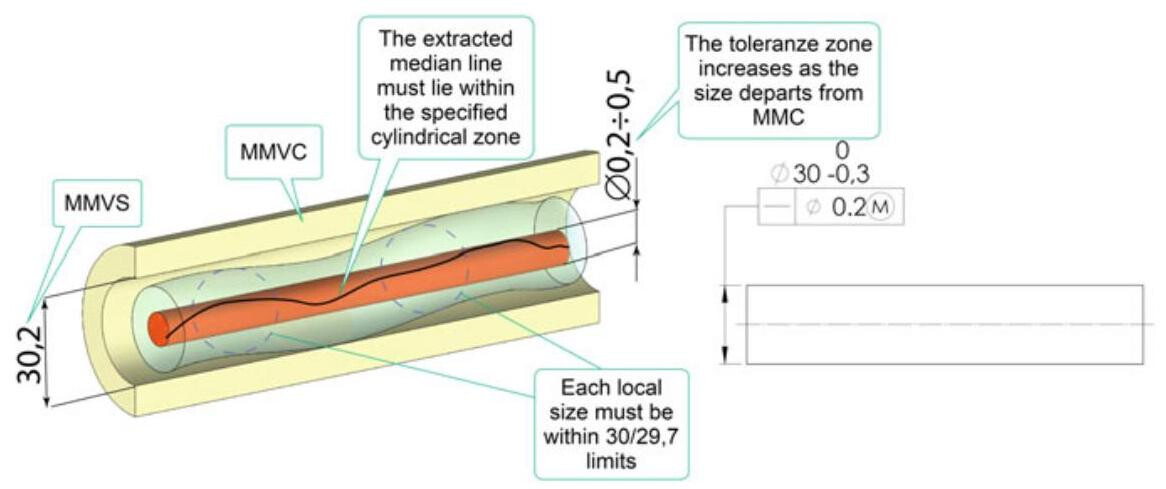
Fig. 7.10 When a straightness control is applied to a feature of size, it is possible to use the maximum material requirement. The combined effect of the size error and the straightness error generates a virtual size (MMVS), which represents the worst possible mating condition
It is also possible to combine a total straightness tolerance with a straightness tolerance on a specified length. In this case, a composite tolerance frame may be used, as in Fig. 7.12. The derived median line must remain within a 0.4mm diameter cylinder along the entire length,but should not exceed 0.1mm for each 25mm of length.
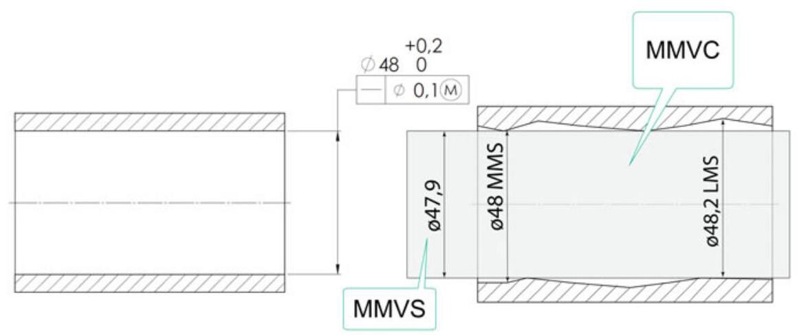
Fig. 7.11 In the case of a hole, the maximum material conditions are those that correspond to the minimum diameter (MMS), and the virtual condition MMVC is always represented by the worst mating conditions, that is, those obtained by subtracting the geometrical tolerance value from the minimum diameter
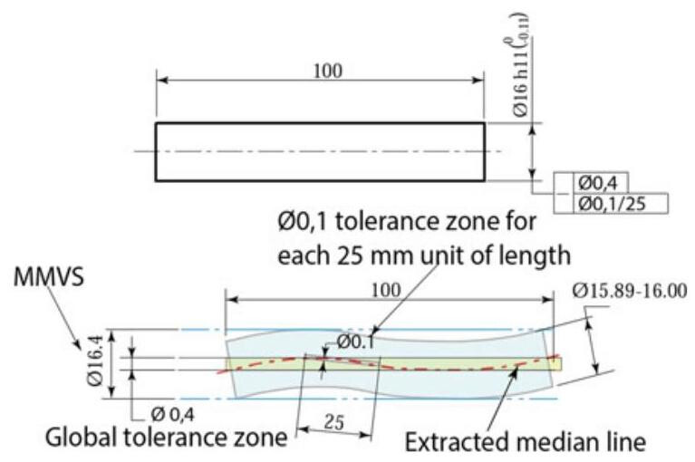
Fig. 7.12 Indications of the straightness tolerance on an axis, with specification of the total straightness and straightness per unit of length: the extracted median line should remain within a 0.4mm diameter tolerance zone for the entire length of 100mm and within a 0.1mm zone for each 25mm of length. Each circular element of the surface should fall within the prescribed dimensional tolerance
7.2.3 Straightness Tolerance in the ASME Standards
When a straightness control is applied to a cylindrical surface, by default, according to the ASME Y14.5 standard, the envelope requirement is invoked (Rule #1), and the form of the entire feature should not violate the boundary of perfect form (as in Fig. 7.5). However, it is necessary to pay particular attention, because whenever the straightness tolerance is applied to a derived median line, Rule #1 is no longer applicable, that is, the component does not have a perfect form at the maximum material. The straightness tolerance frame in Fig. 7.13 is associated with a cylindrical feature of size, and the straightness control therefore applies to the derived median line.
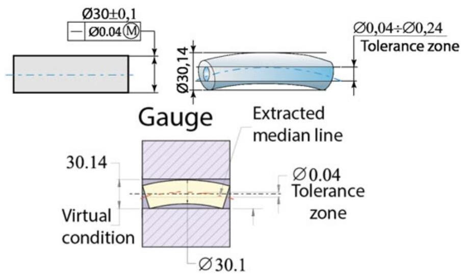
Fig. 7.13 Whenever straightness is specified on an MMC basis, functional gauging techniques may be used
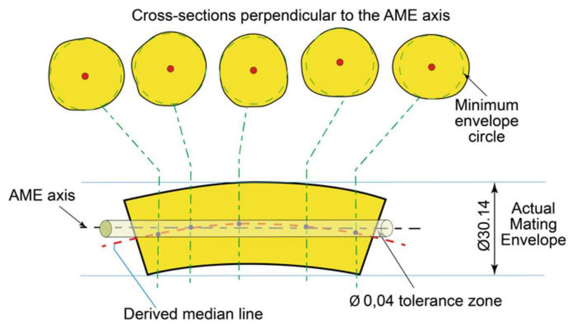
Fig. 7.14 The concept of derived median line for the case of the shaft of the previous figure. The median line is obtained from a set of central points of all the cross sections of the feature. These cross sections are perpendicular to the axis of the smallest restricted cylinder (Actual Mating Envelope)
The application of MMC is helpful since the virtual condition defines the fixed size of the functional gauge that should be used for the verification of a straightness error.
Figure 7.14 shows the concept of a derived median line in the ASME standards, obtained from the set of central points of the singular perpendicular sections of the axis of the smallest restricted cylinder (AME): the derived median line should fall within a cylinder centred on the nominal axis of an envelope of perfect form.
Figure 7.15 shows the use of a straightness tolerance on a flat surface to control line elements in multiple directions. Each line element of the surface should lie between two parallel lines separated by the amount of the prescribed straightness tolerance and in a direction indicated in the orthographic view or by the supplemental geometry of the model. In ASME Y14.5:2018, the supplementary geometry in the annotated model makes the use of the intersection plane (used in the ISO standard) unnecessary.
7.3 Flatness Tolerance
Flatness represents the condition of a surface which has all its points belonging to the same plane: the flatness error is constituted by the deviation of the real surface points from the plane. A flatness tolerance specifies a three-dimensional zone, determined by two parallel planes at a distance that is equal to the flatness control tolerance value. The symbol that should be used in the frame is a parallelogram, with its sides inclined at an angle of 60°(Fig. 7.16).
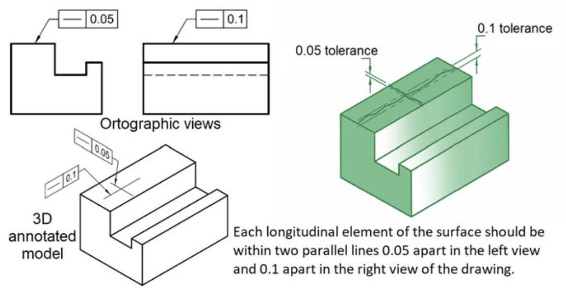
Fig. 7.15 Straightness tolerance on a flat surface used to control line elements in multiple directions. In the ASME Y14.5:2018 standard the supplementary geometry in the annotated model avoids the need to use the intersection plane of the ISO standards
Figure 7.17 shows an example of a component to which a flatness tolerance of 0.1 has been applied: in order to pass the control, the entire surface should fall between two parallel planes 0.1mm apart. In this case,the flatness tolerance is included in the size tolerance of 0.2mm .
It is not possible to apply the maximum or minimum material requirement to a flatness tolerance, as the form tolerance controls all the points of a surface, which is not a sizable feature.
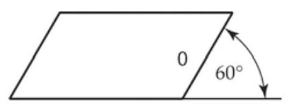
Fig. 7.16 Flatness symbol
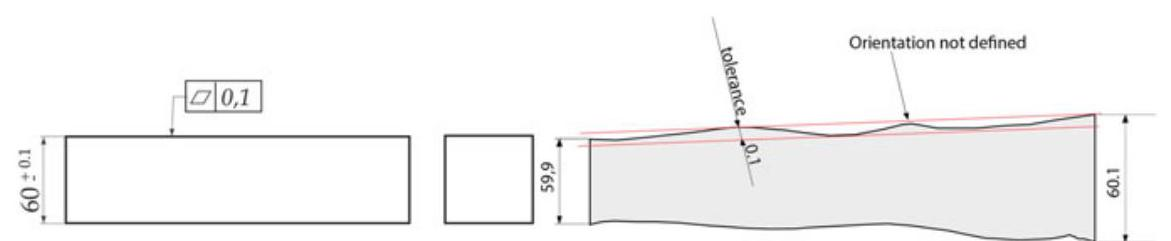
Fig. 7.17 Indication of a flatness tolerance and its interpretation
7.3.1 Flatness Parameters
The ISO 12781 standard defines the terms and concepts necessary to define specification operators (according to ISO 17450-2) for the flatness of integral features.
According to this standard, the extracted surface is a digital representation of the real surface. The flatness surface is an extracted surface intentionally modified by a filter. In the evaluation of the flatness deviation of an integral feature with a given tolerance, the flatness surface should fall between two planes, that are distant from each other by a value that is less than or equal to the specified tolerance value.
When determining the orientation of the tolerance zone, it is necessary to establish a reference plane, that is, an associated plane that fits the flatness surface according to the specified conventions, to which the deviations from flatness and the flatness parameters refer. The ISO 12781-1 technical specification considers two procedures for the determination of the reference plane:
- The minimum zone reference planes method (MZ), which best satisfies the tolerance zone definition (Fig. 7.18) with two parallel planes that enclose the flatness surface and have the least separation.
- The least squares reference plane method (LS), which provides a good approximation of the flatness deviation (Fig. 7.19), although overestimating it, and is currently the most frequently used method in coordinate measuring machines.
Local flatness deviation is defined as the deviation of a point on a flatness surface from the reference plane, in a direction normal to the reference plane.
Some of the terms related to flatness parameters are presented hereafter:
(1) Peak-to-valley flatness deviation, which is the value of the largest positive local flatness deviation that is added to the absolute value of the largest negative local flatness deviation. The GT modifier is used in specifications to indicate that a form tolerance applies to the peak-to-valley deviation relative to the least squares reference element.
(2) Peak-to-reference flatness deviation, which is the value of the largest positive local flatness deviation from the least squares reference line.
(3) Reference-to-valley flatness deviation, which is the absolute value of the largest negative local flatness deviation from the least squares reference line.
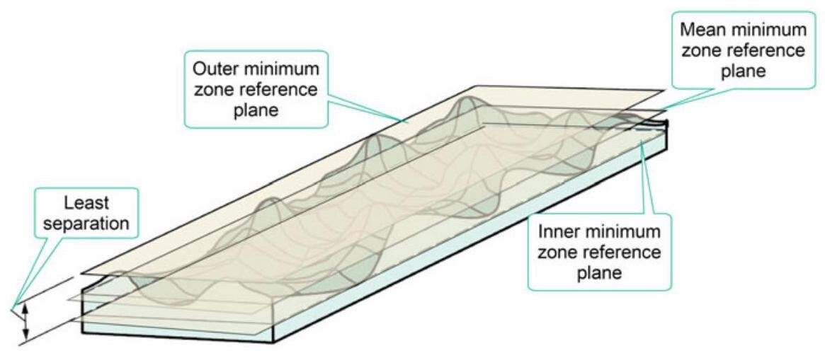
Fig. 7.18 The minimum zone reference plane method with two parallel planes that enclose the flatness surface with the least separation
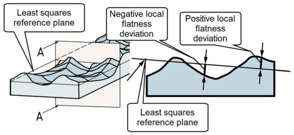
Fig. 7.19 Least squares reference plane
igure 7.20 shows the application of a flatness tolerance to a flat surface (feature integral). As the principle of independency comes into force by default, the following rules are valid:
- the maximum extreme boundary MMVC is obtained by summing the maximum material dimension with the flatness tolerance.
- The flatness tolerance may be larger than the associated dimensional tolerance and each local dimension should fall within the limits of the dimensional tolerance.
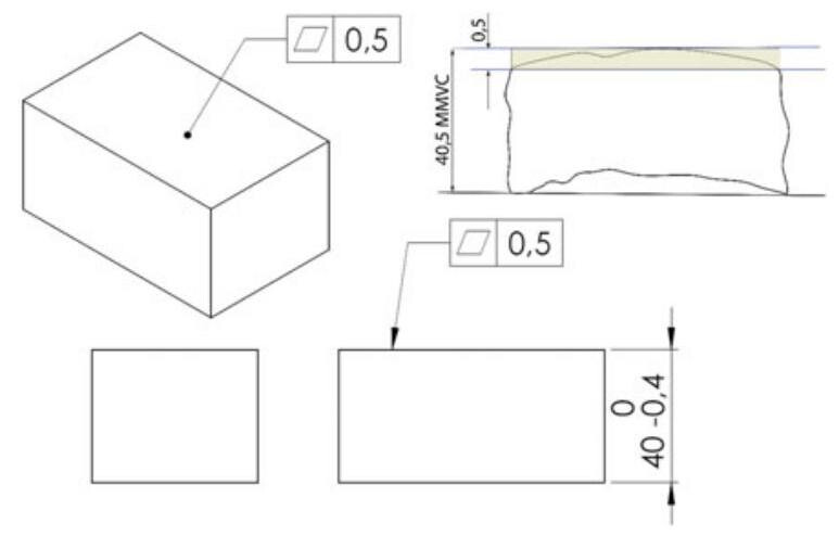
Fig. 7.20 Application of a flatness tolerance to a flat surface of a prismatic component. As the principle of independency comes into force by default, the MMVC is obtained by summing the maximum material dimension with the flatness tolerance, which may be greater than the dimensional tolerance
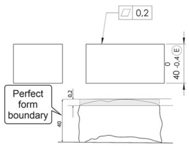
Fig. 7.21 When the envelope requirement (circled E symbol next to the diameter value) is applied, the flatness should be perfect when the component is produced at the maximum material size and the geometrical tolerance should always be less than the dimensional one
When the envelope requirement (circled E symbol next to the value of the diameter) is applied, the flatness should be perfect when the component is produced at the maximum material condition (Fig. 7.21) and the geometrical tolerance should be less than the size tolerance value. It should be recalled that this case constitutes the default condition in the ASME standards. Design experience led to the conclusion that it is advisable to prescribe a flatness tolerance that is no greater than half of the associated tolerance dimension. A flatness tolerance is usually adopted to qualify a primary datum feature.
7.3.2 Flatness Control
Several different methods may be used to check a flatness specification. For example, a flatness error can be controlled by moving a dial indicator over the entire surface, and the error is revealed as the difference between the maximum and minimum obtained measurements (Fig. 7.22a). The orientation of the plate is obtained through the use of opportune gauge blocks, and the measurement should be repeated continuously; in fact, flatness does not control a geometrical error of orientation. This method may be time consuming since the metrologist should avoid the influence of the orientation on the measurement.
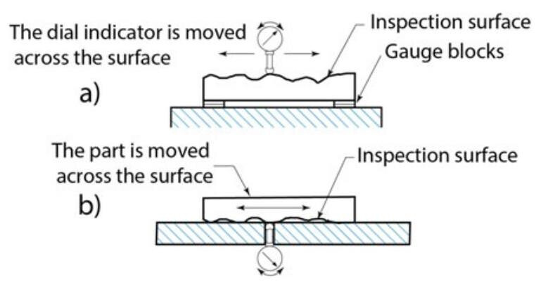
Fig. 7.22 Inspecting flatness: a control of the flatness error by means of an adjustable support or b by means of a dial indicator placed below the surface plate
In order to avoid this problem, it is possible to use the method shown in Fig. 7.22b, that is, the part is placed on a surface plate that has a small hole. The dial indicator is placed into the small hole below the surface plate, and the part is moved in all directions. Unfortunately, if the surface is convex, it is difficult to determine the minimum indicator reading over the entire surface.
The measurement accuracy of the flatness defect can be improved by using a coordinate measuring machine (CMM) with a suitable fitting criterion. The Minimum Zone method of evaluating flatness is the most accurate and one that is best able to satisfy the ISO and ASME standards. In this case, the software of the CMM creates two theoretical parallel planes, which sandwich the extracted points as tightly as possible, and then calculates the distance between them.
7.3.3 Flatness Tolerance in the ASME Standards
In the case of the ASME standard, since the envelope requirement (Rule #1) is called into force by default, the use of the flatness tolerance has the purpose of limiting the error when the workpiece is produced with dimensions close to the least material condition (Fig. 7.23). Basically, the flatness specification further restricts the form control provisions of Rule #1.
The ASME standard of 2009 introduced the possibility of using the flatness tolerance to control the error of a derived median plane. In this case, the frame is applied to the height dimension of the workpiece, and it is possible to use the maximum material conditions (Fig. 7.24). The derived median plane should be contained between two parallel lines 0.04 apart, and each surface feature should fall within the dimensional tolerance. Figure 7.25 shows a typical application for the control of a curvature error of a plate. By applying the flatness tolerance to the thickness dimension of the plate, it is possible to control the flatness error of the derived median plane. A functional gauge is obtained from the virtual conditions \left( {{16} + {0.04}\mathrm{\;{mm}}}\right) .
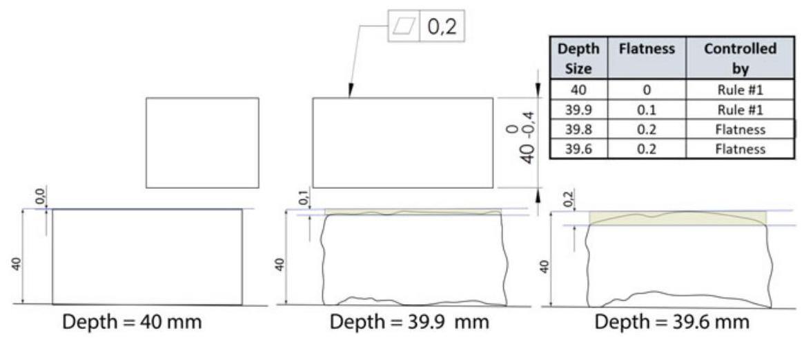
Fig. 7.23 In the case of the ASME standard, since the envelope requirement comes into force by default, the use of the flatness tolerance has the purpose of limiting the error when the workpiece is produced with dimensions close to the least material size. The flatness tolerance zone falls within the dimensional error
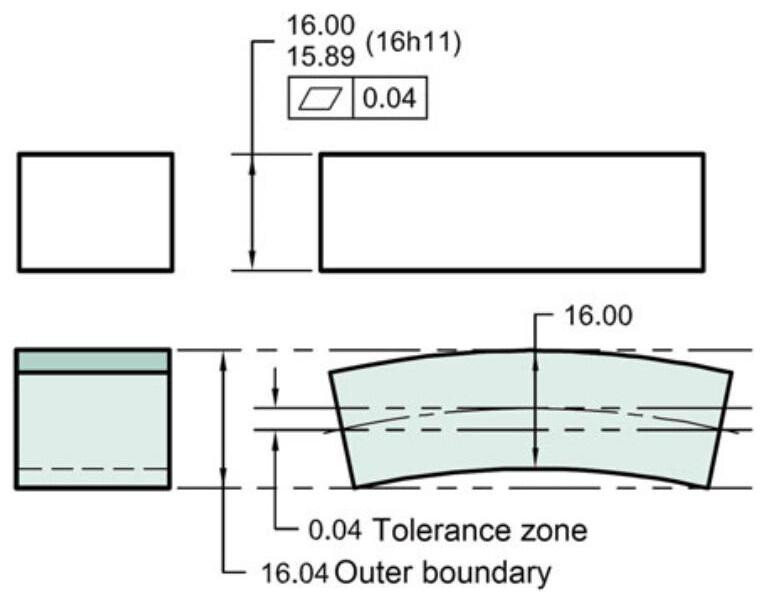
Fig. 7.24 Use of the flatness tolerance to control an error of a derived median plane. In this case, the tolerance frame is applied to the height dimension of the workpiece, and it is possible to use the MMC modifier
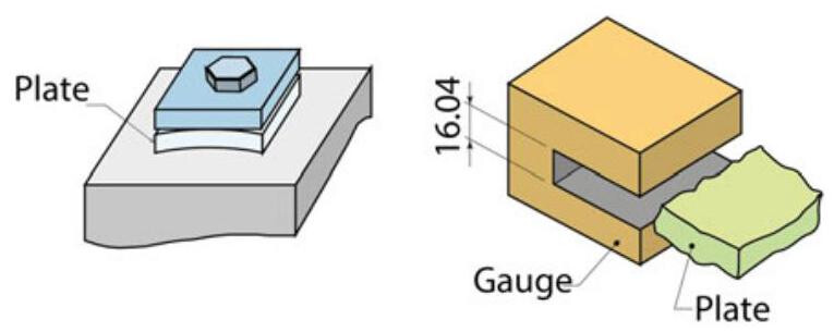
Fig. 7.25 By applying the flatness tolerance to the thickness dimension of the plate, it is possible to control the flatness error of the derived median plane. The control gauge is obtained from the virtual conditions \left( {{16} + {0.04}\mathrm{\;{mm}}}\right)
7.4 Roundness
Roundness (‘circularity’ in the ASME standards) is a property of a circle. Roundness, to be more precise, is the condition at which all the points of a revolution surface are equidistant from the axis, at each section perpendicular to a common axis. A roundness error occurs when the sections made perpendicular to the axis of a round symmetry workpiece (which should nominally be circumferences) are oval, elliptic or in some way irregular.
A roundness tolerance specifies a bi-dimensional zone limited by two coaxial circles placed at a distance which is radially equal to the specified tolerance.
For cylindrical features, roundness applies for cross-sections perpendicular to the axis of the toleranced feature. For spherical features, roundness applies for cross-sections that include the centre of the sphere. A direction feature should always be indicated for revolute surfaces that are neither cylindrical nor spherical.
The example in Fig. 7.26 shows the case of indications of a roundness tolerance of 0.2 on a cylindrical workpiece; the tolerance zone falls between two concentric circles 0.2mm apart. It should be noted that the tolerance zone is established relative to the dimensions of a transversal section, and as the ISO 8015 standard comes into force by default (and therefore the principle of independency), the dimensional and geometrical tolerances lead to an extreme boundary condition of 10.2mm(10+ 0.2). The following rules are valid for the correct interpretation of drawings:
(1) the control of roundness is applied to all the cross sections along the toleranced feature;
(2) the roundness error may be greater than the dimensional tolerance applied to the corresponding diametric dimension;
(3) each local dimension should fall within the dimensional tolerance limits;
(4) a Maximum Material Virtual Size (MMVS) is obtained.
In the same way as for the flatness case, it is advisable, as a general rule, to choose a tolerance of a value that is less than half that of the dimensional tolerance; moreover, it is not possible to apply a maximum material or least material modifier, in that the roundness tolerance controls the boundary points of a transversal surface, a feature that cannot be sized.
The roundness error may be associated with conic surfaces or surfaces of any form, but always on condition they have round sections, as shown in Fig. 7.27.
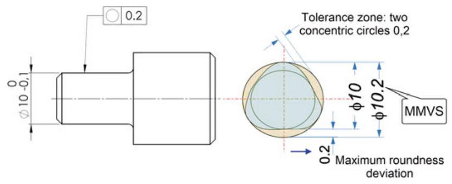
Fig. 7.26 Indication and interpretation of a roundness tolerance
Fig. 7.27 Roundness tolerance applied to an axial-symmetric workpiece. The extracted circumferential line should be contained between two circles (0.04 mm apart) in any cross-section perpendicular to datum axis A, as indicated by the direction feature symbol
7.4.1 Roundness Parameters
The ISO 12181 standard defines the terms and concepts necessary to define specification operators (according to ISO 17450-2) for the roundness of integral features.
According to this standard, the extracted circumferential line is a digital representation of the intersection of the real surface and a roundness plane while the roundness profile is an extracted circumferential line intentionally modified by a filter. The roundness plane is a plane that is perpendicular to the roundness axis for the full extent of the feature, while the roundness axis is the axis of a feature associated with an integral feature.
When evaluating the roundness deviation of an integral feature with a given tolerance, the roundness profile should fall between two circles that are distant from each other by a value that is less than or equal to the specified tolerance value.
When determining the roundness deviation, it is necessary to establish a reference circle, that is, an associated circle that fits the roundness profile according to specified conventions, to which the deviations from roundness and the roundness parameters refer. The inspection of roundness, by means of CMM measuring machines, foresees, starting from the extracted line, the association of a reference circle, with respect to which two concentric circles can be defined in order to calculate the magnitude of the tolerance zone that contains the circle itself.
The ISO 12181-1 technical specification considers four procedures that can be used to determine the reference circle:
- The minimum zone reference circles method (MZ), whereby two concentric circles enclose the roundness profile and have the least radial separation (Fig. 7.28).
- The least squares reference circle (LS), that is, a circle in which the sum of the squares of the local roundness deviations is a minimum (Fig. 7.29).
- The minimum circumscribed reference circle (MC), that is, the smallest possible circle that can be fitted around the roundness profile (Fig. 7.30).
- The maximum inscribed reference circle (MI), that is, the largest possible circle that can be fitted within the roundness profile (Fig. 7.31).
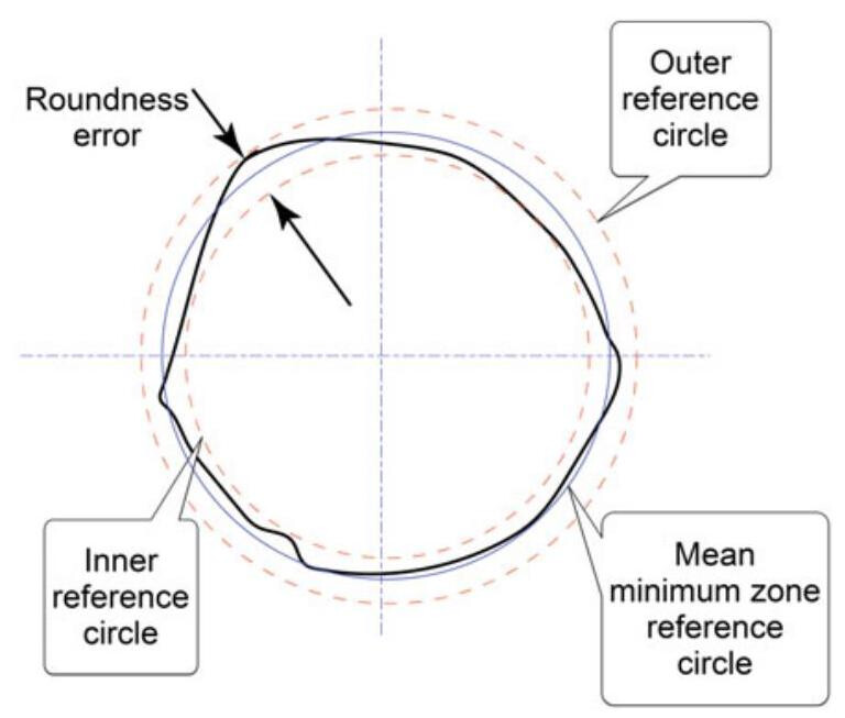
Fig. 7.28 The minimum zone reference circle method with two concentric circles which enclose the roundness profile and have the least radial separation. The roundness error is the radial distance between the two circles
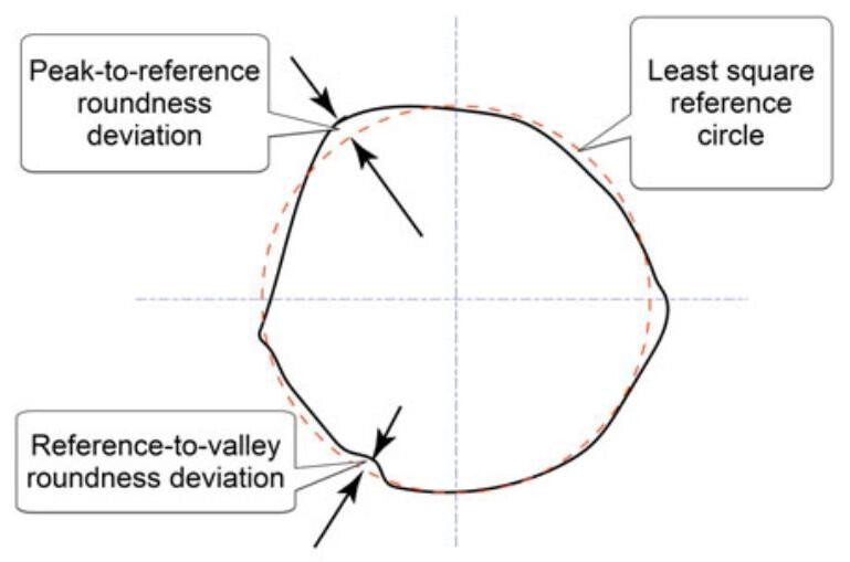
Fig. 7.29 Least square reference circle. The roundness error is expressed as the sum of the largest positive local roundness deviation and the absolute value of the largest negative local roundness deviation
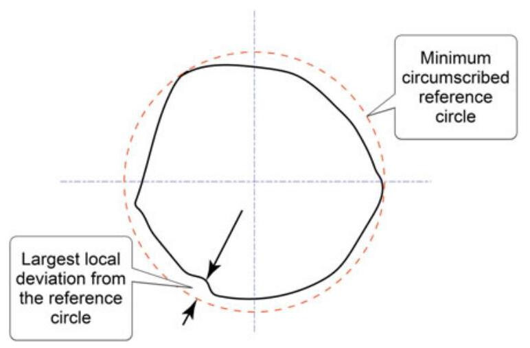
Fig. 7.30 The minimum circumscribed reference circle (MC), that is, the smallest possible circle that can be fitted around the roundness profile. The roundness error is the largest local deviation from the reference circle
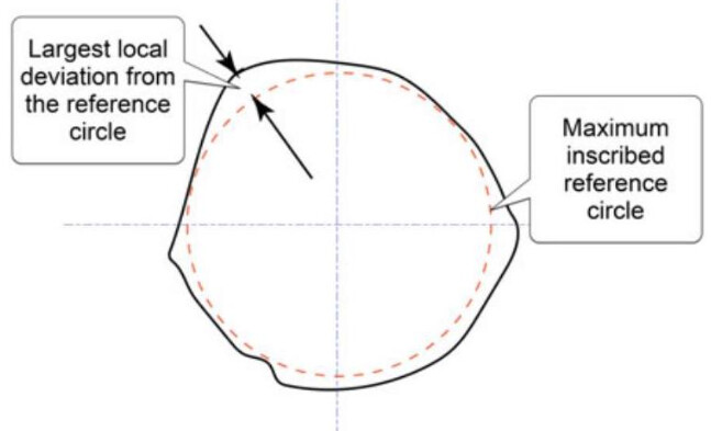
Fig. 7.31 The maximum inscribed reference circle (MI), that is, the largest possible circle that can be fitted within the roundness profile. The roundness error is the largest local deviation from the reference circle
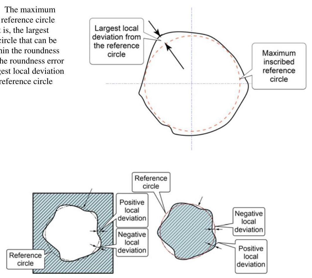
Fig. 7.32 The local form deviation of an internal feature and of an external roundness feature
Local roundness deviation is defined as the minimum distance between a point on a roundness profile and the reference circle (Fig. 7.32).
Some of the terms related to roundness parameters are presented hereafter:
(1) Peak-to-valley roundness deviation, which is the value of the largest positive local roundness deviation added to the absolute value of the largest negative local roundness deviation. The GT modifier is used in specifications to indicate that a form tolerance applies to the peak-to-valley deviation relative to the least squares reference element.
(2) Peak-to-reference roundness deviation, that is, the value of the largest positive local roundness deviation from the least squares reference line.
(3) Reference-to-valley roundness deviation, that is, the absolute value of the largest negative local roundness deviation from the least squares reference line.
The control of roundness may be achieved by means of coordinate measuring machines, or through the use of other systems, such as the roundness checking machine shown in Fig. 7.33, which is composed of three main features, a high-precision spindle, a probe and a computer.
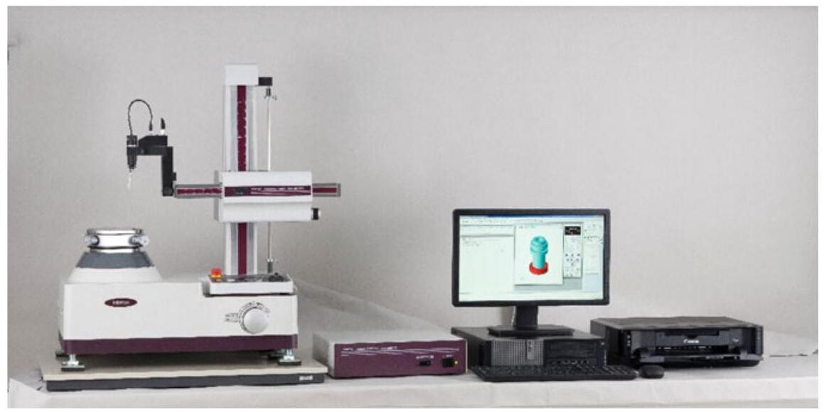
Fig. 7.33 Measurements may be carried out by means of a roundness checking machine, such as the one shown here (Mitutoyo RA-1600 M Roundness Tester)
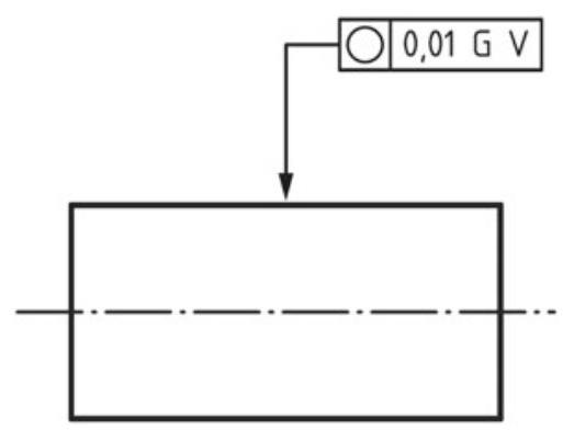
Fig. 7.34 Specification using the least squares (Gaussian) reference feature specification element and the valley depth characteristic specification element
In the past, the definition of the reference circle was left to the discretion of the measurement technicians who, on many occasions, applied the GPS default, that is, the minimum zone criterion (Chebyshev). However, with the new ISO 1101 standard of 2017, it is possible to apply a further series of criteria that can be adopted for all form controls and which can be identified by means of modifiers, as shown in Fig. 7.34.
7.4.2 Roundness Tolerance in the ASME Standards
In the case of the ASME standards, since the envelope requirement is valid by default, the use of circularity tolerance has the purpose of limiting the error when the workpiece is produced with dimensions close to the least material condition (see Fig. 4.25). The geometrical tolerance should always be less than the dimensional tolerance of the inspected feature, and the same effect is obtained with ISO using the symbol E closed within a circle. In Fig. 7.35, each circular element of the surface, on a plane perpendicular to the axis of the unrelated AME, should fall within two concentric circles 0.25mm apart. Moreover,each circular element of the surface should be within the specified limits of size. However, according to the general principles of the ASME standards, no mention is made of how the roundness should be measured.
For flexible revolute components in a non-restrained condition, it is possible to specify an average diameter with the abbreviation “AVG”, that is, the average of several diametric measurements across a circular or cylindrical feature. The individual measurements may violate the limits of size, but the average value should fall within the limits of size (Fig. 7.36). Moreover, the circularity tolerance can be greater than the size tolerance on the diameter.
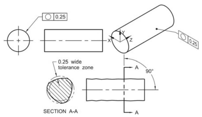
Fig. 7.35 Each circular element of the surface, on a plane perpendicular to the axis of the unrelated AME,should fall within two concentric circles 0.25mm apart
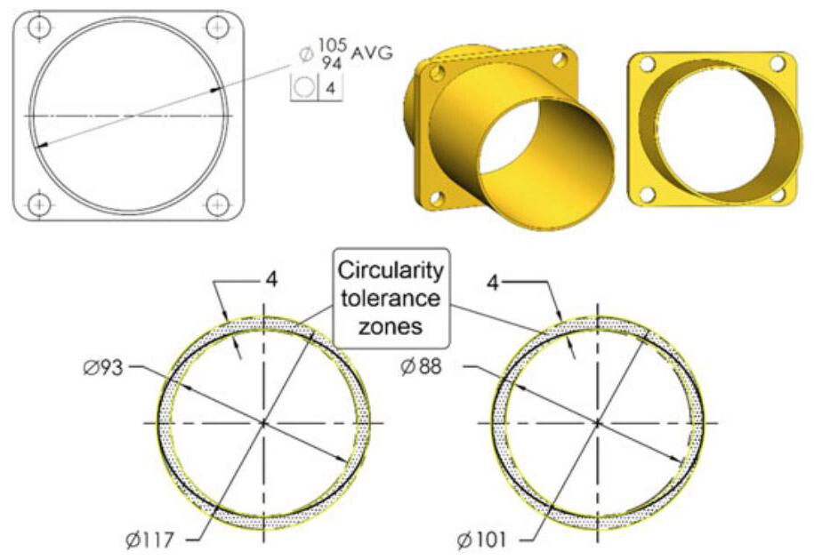
Fig. 7.36 Specifying Circularity with the average diameter
7.5 Cylindricity
Although various sections with planes perpendicular to the axis of a workpiece are circumferences, there may be differences in diameter among them; cylindricity is in fact a condition of a revolution surface in which all the points of the surface are equidistant from a common axis.
The symbol that should be placed in the tolerance frame to indicate a cylindrical tolerance is shown in Fig. 7.37.
A real cylindrical surface can be subject to deviation errors from the cylindrical form as a combination of simple elements, caused by machining errors and/or distortions resulting from thermal, pressure or stress effects, tool wear, and/or vibrations. These deviations may be classified as (Fig. 7.38):
- Median line deviation: the deviation of a nominal cylindrical workpiece which has a curved axis, but a circular and constant radius cross-section.
- Radial deviations, i.e. variations in the cross-section dimension: the deviation of a nominal cylindrical workpiece which has all the cross-sections circular and concentric to a straight axis, but whose diameters vary along the axis according to simple or complex laws or even randomly (typical deviations include conical, barrel or more complex forms).
- Cross-section deviations: the deviation on a nominal cylindrical workpiece that has cross-sections of the same size and form, but which are not round.
A cylindrical tolerance specifies a three-dimensional zone between two coaxial cylinders within which the surfaces should fall. The example in Fig. 7.39 shows a cylindrical shaft with a cylindricity tolerance of 0.03mm,which is measured in a radial direction, that is, through coaxial cylinders 0.03 apart.
Fig. 7.37 The cylindricity symbol
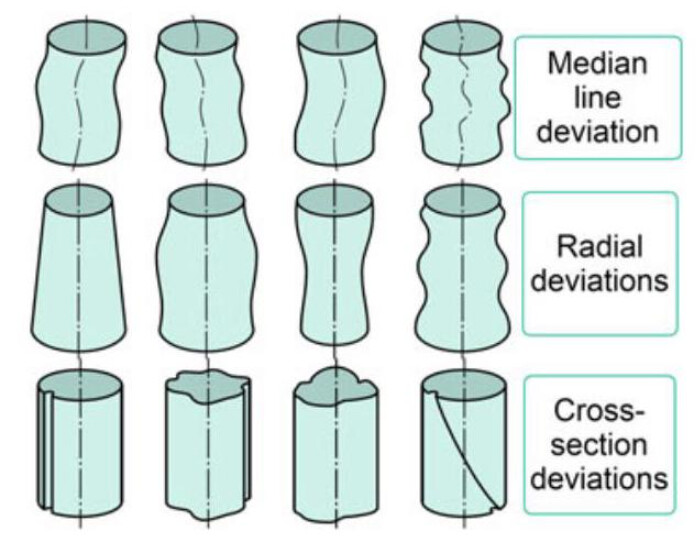
Fig. 7.38 Deviations from cylindrical form
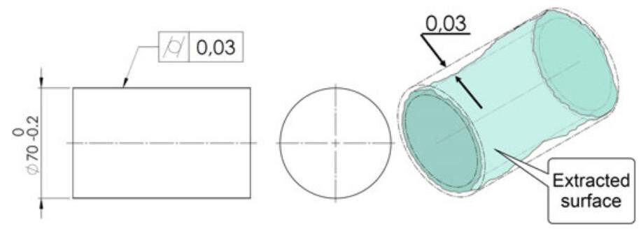
Fig. 7.39 Cylindrical tolerance and its interpretation
Since a cylindricity tolerance can be interpreted as a roundness tolerance that is extended over the entire cylindrical surface, it can be used to control the roundness, the straightness and the taper of the surface features simultaneously.
Again in this case, it is advisable to choose a form tolerance of a value that is less than half of the dimensional tolerance; moreover, the maximum material requirement cannot be applied, as a cylindrical surface is not a sizeable feature. Cylindricity can be inspected in a similar manner to the way roundness is inspected, that is, utilising a coordinate measuring machine or a specific measuring machine, as shown in Fig. 7.33.
Together with the control of roundness, the example in Fig. 7.40 also shows an example of an indication of cylindricity tolerance of 0.1 on a cylindrical workpiece; the tolerance zone falls between two coaxial cylinders 0.1mm apart. It should be noted that, since the independency principle is called into force by default, the dimensional and geometrical tolerances have a virtual condition of 10.1mm(10+0.1).
The following rules are valid for a correct interpretation of drawings:
(1) the cylindricity error may be greater than the dimensional tolerance applied to the corresponding diametric dimension;
(2) each local dimension should fall between the dimensional tolerance limits;
(3) an extreme boundary of the maximum material (MMVS) is obtained.
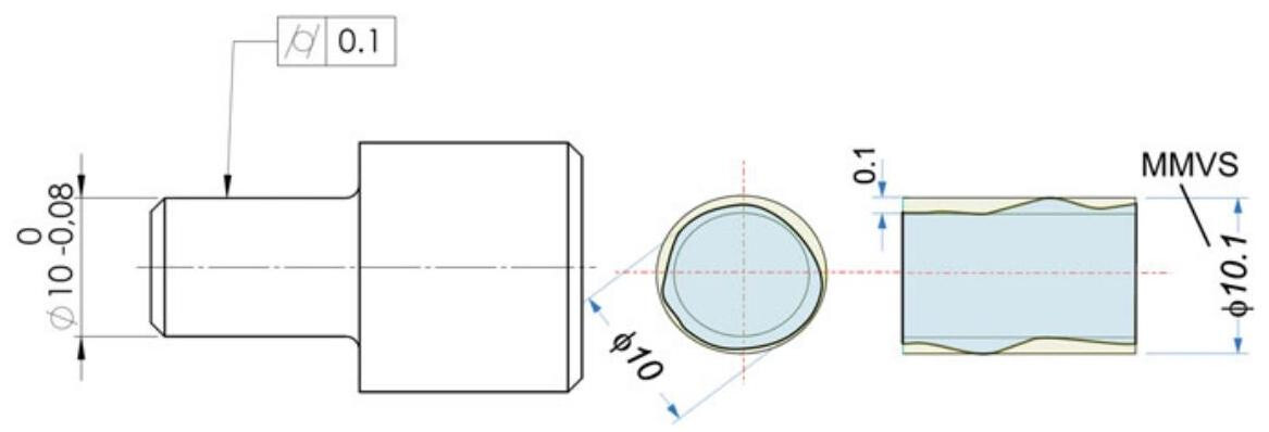
Fig. 7.40 Interpretation of the independency principle for a cylindricity tolerance. A maximum material virtual size (MMVS) of 10.1mm is obtained
7.5.1 Cylindricity Parameters
The ISO 12180 standard defines the terms and concepts necessary to define specification operators (according to ISO 17450-2) for the cylindricity of integral features.
According to this standard, the extracted surface is a digital representation of the real surface, while the cylindricity surface is an extracted surface (of a cylindrical type) intentionally modified by a filter.
The generatrix plane is a half plane that passes through the axis of the associated cylinder, while the extracted generatrix line is a digital representation of the intersection line of the real surface and a generatrix plane.
When evaluating the cylindricity deviation of an integral feature with a given tolerance, the cylindricity surface should fall between two cylinders that are distant from each other by a value that is less than or equal to the specified tolerance value.
When determining the cylindricity deviation, it is necessary to establish a reference cylinder, that is an associated cylinder that fits the cylindricity surface according to specified conventions, to which the deviations from cylindrical form and the cylindricity parameters refer. The associated derived axis of a cylindrical feature is the axis of the reference cylinder(s).
The inspection of cylindricity, by means of CMM measuring machines, foresees, starting from the extracted surface, the association of a reference cylinder, with respect to which two coaxial cylinders can be defined in order to calculate the magnitude of the tolerance zone.
The ISO 12180-1 technical specification considers four procedures that can be used to determine the reference cylinder:
-
The minimum zone reference cylinders method (MZ), that is, two coaxial cylinders enclose the cylindricity surface and have the least radial separation.
-
The least squares reference cylinder (LS), that is, a cylinder for which the sum of the squares of the local cylindricity deviations is the minimum value.
-
The minimum circumscribed reference cylinder (MC), that is, the smallest possible cylinder that can be fitted around the cylindricity surface.
-
The maximum inscribed reference cylinder (MI), that is, the largest possible cylinder that can be fitted within the cylindricity surface.
Local cylindricity deviation is defined as the deviation of a point on a cylindricity surface from the reference cylinder, the deviation being normal to the reference cylinder (Fig. 7.41). The local generatrix deviation is a deviation of a point on a generatrix from the reference line, the deviation being normal to the reference line.
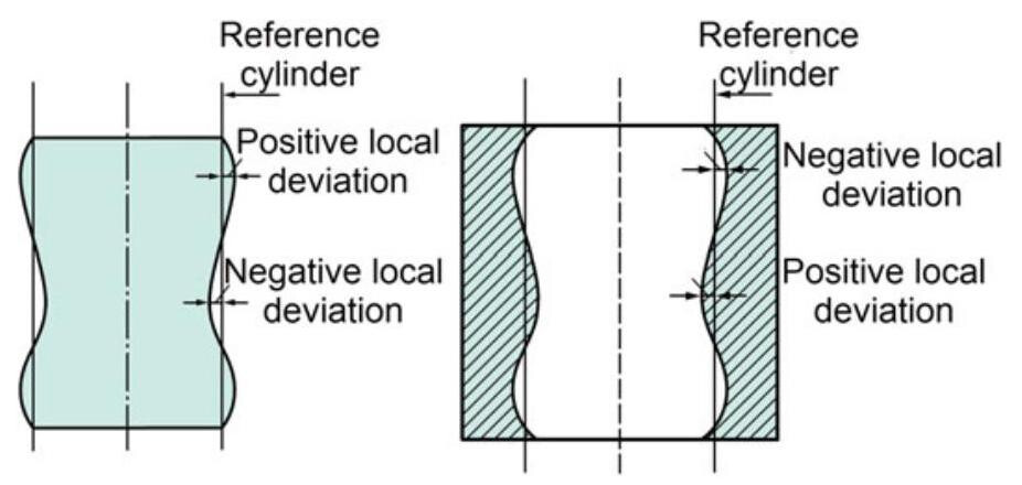
Fig. 7.41 Local form deviations of an external and internal cylindrical feature
The local generatrix straightness deviation is a straightness deviation value calculated from a generatrix profile obtained from an intersection of a plane through the axis of the least squares reference cylinder and the extracted cylindrical feature (Fig. 7.42).
The absolute value \left| {{\mathrm{D}}_{1} - {\mathrm{D}}_{2}}\right|/ 2 is the local cylinder taper value. This parameter is usually evaluated with a length L of 100mm .
Some of the terms related to cylindricity parameters are given hereafter:
(1) Peak-to-valley cylindricity deviation, which is the value of the largest positive local cylindricity deviation added to the absolute value of the largest negative local cylindricity deviation. The GT modifier is used in specifications to indicate that a form tolerance applies to the peak-to-valley deviation relative to the least squares reference element.
(2) Peak-to-reference cylindricity deviation, which is the value of the largest positive local cylindricity deviation from the least squares reference cylinder.
(3) Reference-to-valley cylindricity deviation, which is the absolute value of the largest negative local cylindricity deviation from the least squares reference cylinder.
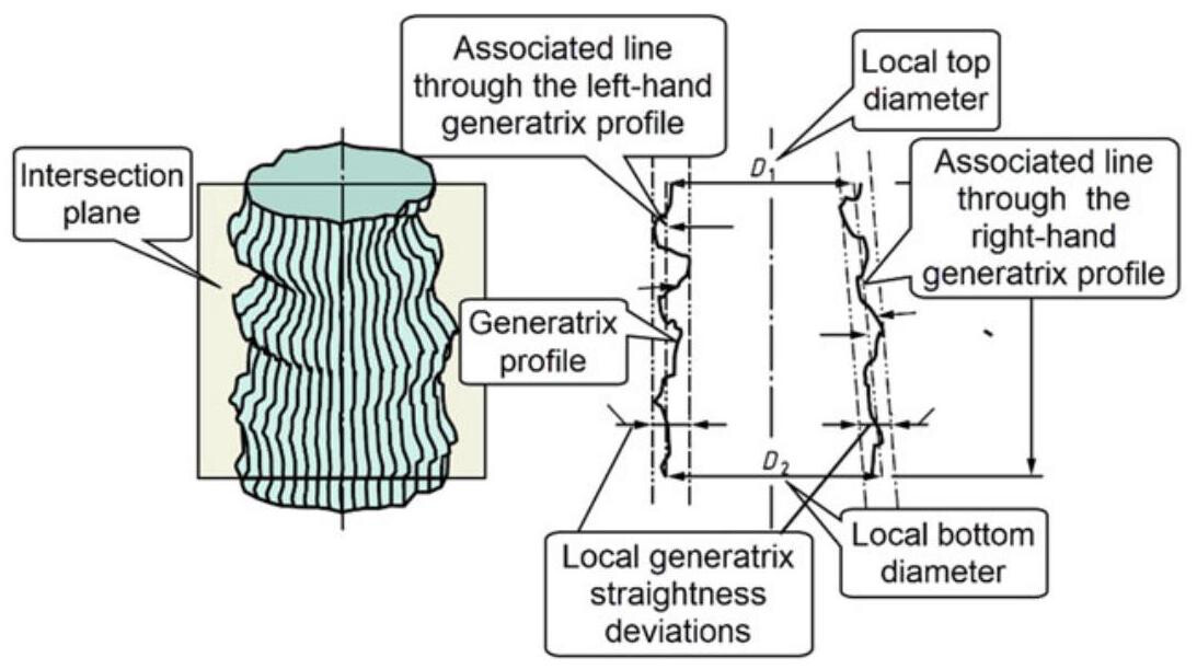
Fig. 7.42 Local generatrix straightness deviations
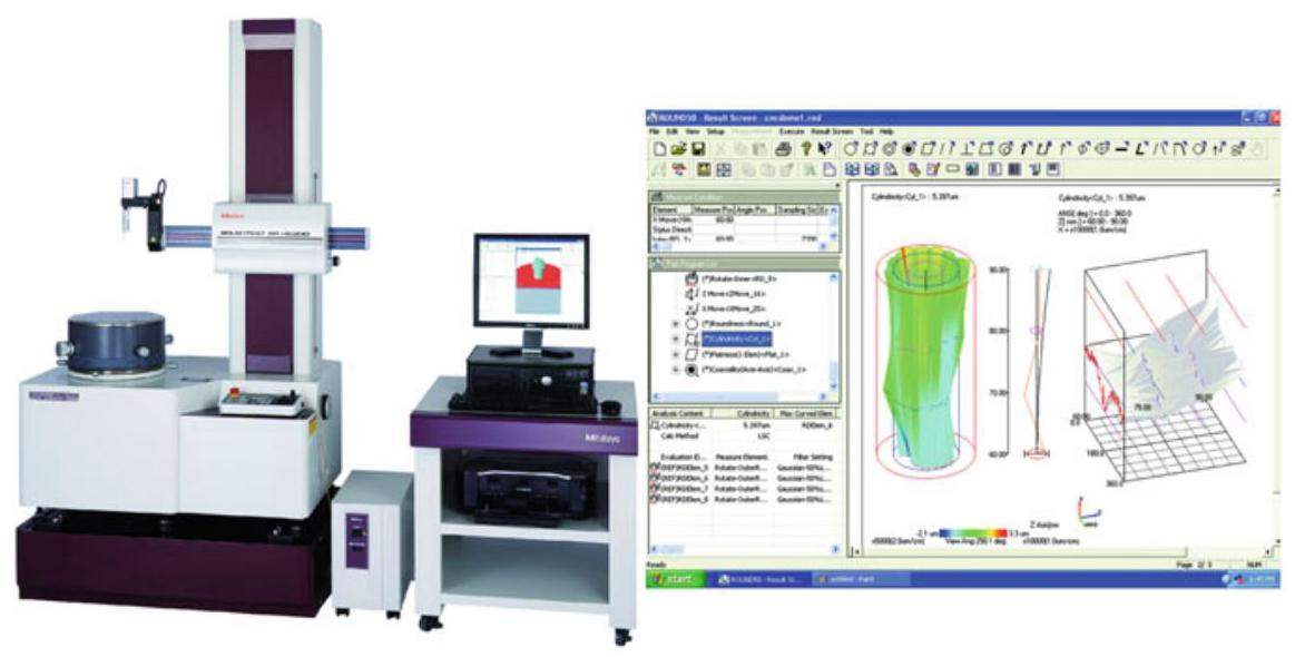
Fig. 7.43 Cylindricity inspection with a CNC form measuring instrument (Roundtest Extreme RA-H5200CNC, Mitutoyo)
The control of cylindricity may be achieved by means of coordinate measuring machines, or through the use of other systems, such as the “Roundtest Machine” shown in Fig. 7.43, which is a CNC form measuring instrument that combines high accuracy with automatic CNC measurements.
Again in this case, it is possible to indicate the reference cylinder association methodology, from which it is possible to derive two coaxial cylinders, which can be used to obtain the cylindricity measurement. The association shown in Fig. 7.44 is in fact obtained with the smallest circumscribed cylinder (N and X modifiers).
7.5.2 Cylindricity Tolerance in the ASME Standards
In the case of the ASME standard, since the envelope requirement (Rule #1) is called into force by default, the use of the cylindricity tolerance has the purpose of limiting the error when the workpiece is produced with dimensions close to the least material condition (Fig. 7.45). Basically, the cylindricity specification further restricts the form control provisions introduced by Rule #1.
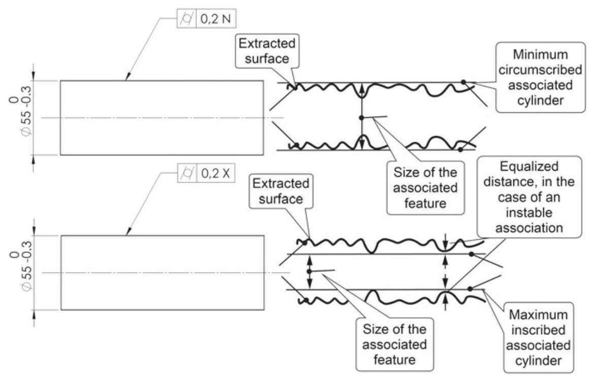
Fig. 7.44 Specification of the reference cylinder association methodology
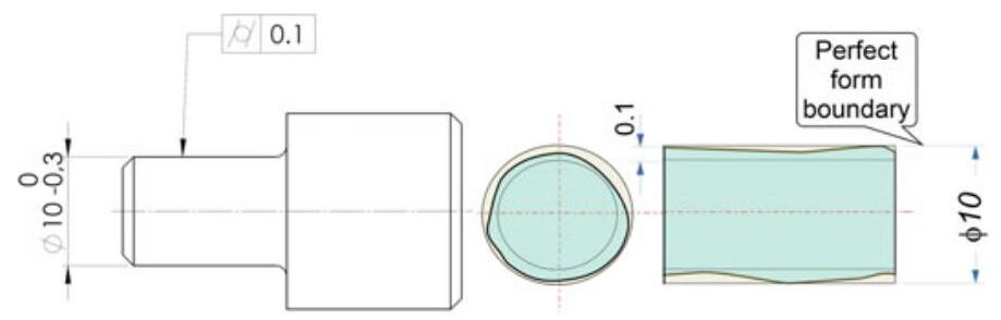
Fig. 7.45 Indication and interpretation of a cylindricity error in the ASME standards. The geometrical tolerance should always be less than the dimensional tolerance of the inspected feature, and the same effect can be obtained with ISO using the symbol E enclosed within a circle