Abstract A datum system has the purpose of defining a set of two or more ideal features established in a specific order (for example, a system made up of a triad of mutually orthogonal planes) that allows not only the tolerance zones to be orientated and located, but also their origin to be defined for the measurement, and the workpiece to be blocked during the control. When it is not desirable to use a complete integral feature to establish a datum feature, it is possible to indicate portions of the single feature (areas, lines or points) and their dimensions and locations using datum targets. This chapter illustrates the main differences between the ISO 5459 and ASME standards for the specification of datums and highlight some theoretical and mathematical concepts. This section also provides simple rules to follow whenever choosing functional datums to ensure the part will function as intended, with the least possible amount of variation.
6.1 Datum Systems
A datum system represents one of the most advantageous instruments to pass on information about functional relationships and, at the same time, to transmit the modalities and sequences with which the control of the component should be carried out in such a way that the inspection measurement is univocal and repeatable.
The greatest disadvantage of the use of a datum system is that an adequate knowledge of the geometrical tolerance standards is necessary. In fact, a lack of attention to the functional aspects of geometrical dimensioning has led to some datum misconceptions. The first of these concerns the conviction that datums exist on a part, although the planes and axes taken as datums are in fact abstract concepts that are obtained through complex verification operations.
Another misconception is that datums are established directly during the manufacturing design phase; in fact, the datums derived from operational requirements often do not agree with the ones that are fixed during the design phase on the basis of the functional requirements. If a process engineer introduces any modifications, the functional requirements will no longer be respected, because of changes in the tolerances (which often become more reduced).
A datum should always be selected on the basis of the functions of a part, since choosing datums on the basis of the technological location of the workpieces can lead to a reduction in the available tolerances.
A datum system (known as DRF, Datum Reference Frame in the ASME standards) is a set of two or more ideal features established in a specific order from two or more datum features, with the aim of (Fig. 6.1):
- defining the origin from which the location or geometric characteristics of the features of a part are established;
- allowing the workpiece to be blocked during a control, so that the control is univocal and repeatable;
- locating and orienting the tolerance zones.
In short, datums allow a datum system to be defined for the dimensioning of a drawing and they can be considered as a way of blocking the degrees of freedom of a tolerance zone.
The ISO 5459 standard specifies the terminology, rules and methodologies pertaining to the indication and comprehension of datums and of datum systems in the technical documentation of a product. The physical surfaces of real and imperfect parts are defined as datum features in the standard as they serve the purpose of constraining the rotational and translational degrees of freedom during the assembly processes and which can be used to define the datums (Fig. 6.2). In fact, each workpiece is considered to be made up of features that can have a size and an axis, or a symmetry plane (a feature of size such as a groove, a hole or a pin), or non-dimensional features such as flat or cylindrical surfaces; as each feature can be considered as a datum, it is possible to have datums correlated to both sizeable and non-sizeable features, which are indicated on a drawing in different ways.
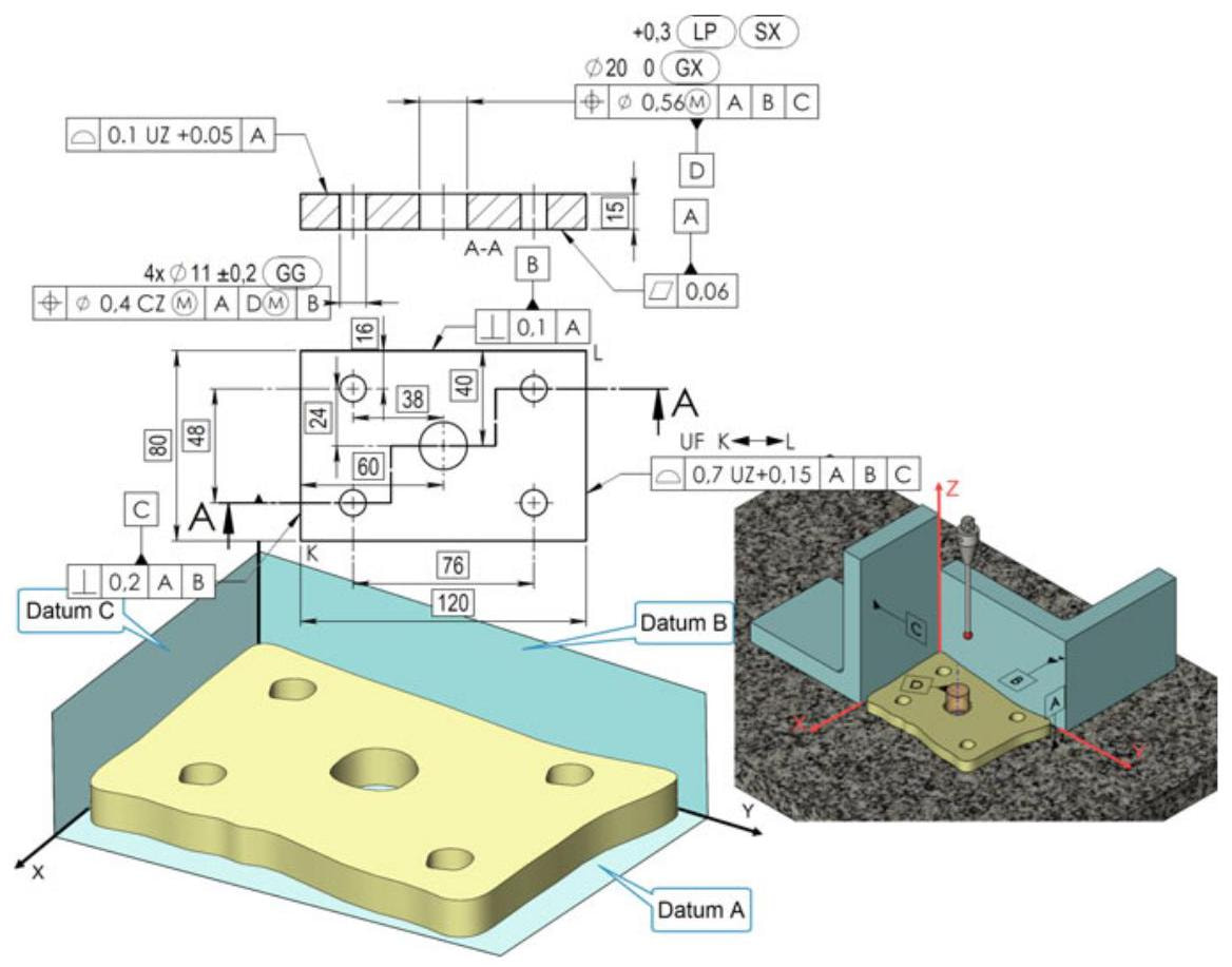
Fig. 6.1 A datum system has the purpose of defining a set of two or more ideal features, established in a specific order (for example, a system made up of a triad of mutually orthogonal planes), that allows not only the tolerance zones to be orientated and located, but also their origin to be defined for the measurement, and the workpiece to be blocked during the control
A datum is a theoretically exact point, straight line, or plane from which the location and orientation of features, or both, can be defined (Fig. 6.3). A datum specification refers to the concept of a situation feature, which is obtained through an association criterion with the datum feature, that is, an ideal feature (plane, point or straight line) is associated with the true (extracted and filtered) surface.
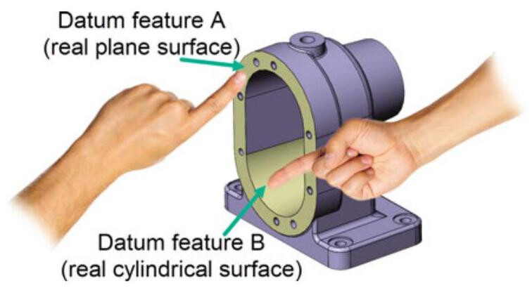
Fig. 6.2 Datum features are particular physical features of real, imperfect, labelled workpieces that have the purpose of constraining the rotational and translational degrees of freedom of relative parts. Datums are the surfaces of the workpiece that can be touched, and they are suitable for associating to a datum
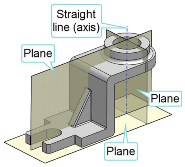
Fig. 6.3 A datum is a theoretically exact point, straight line, or plane from which the location and orientation of features, or both, can be defined
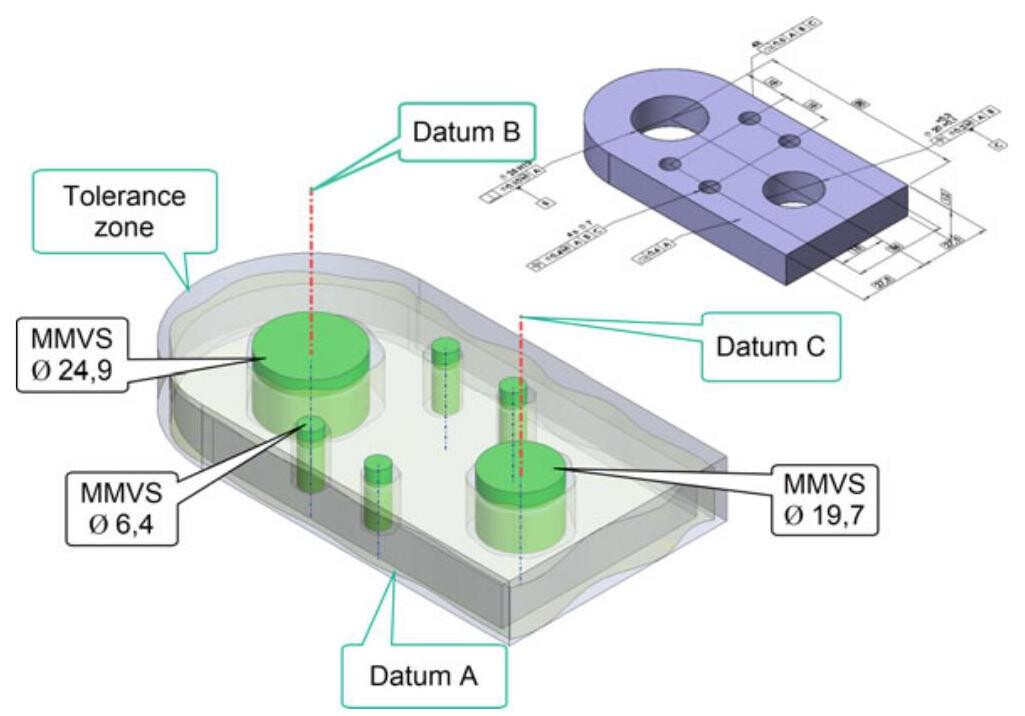
Fig. 6.4 According to ISO 5459, a datum is one or more situation features (plane, point and/or straight line) that is selected to define the location or orientation, or both, of a tolerance zone or an ideal feature that represents, for instance, a virtual condition
In short, a datum is one or more situation features of one or more features associated with one or more real integral features selected to define the location or orientation, or both, of a tolerance zone or an ideal feature that represents, for instance, a virtual condition (Fig. 6.4). Datums allow tolerance zones to be located or orientated and virtual conditions to be defined (for example, the maximum material virtual condition, according to ISO 2692).
6.1.1 Association of Datums
A datum is a theoretically exact point, axis, or plane that is obtained through an association criterion with the datum feature, that is, an ideal feature (plane, point or line) which is associated with the true (extracted and filtered) surface. The objective of such an association is to obtain an unambiguous identification of unique datums or datum systems.
In order to establish an associated feature, it is necessary to first perform a partition, then an extraction, a filtration and, finally, an association. The filtration should retain the highest points of the real integral feature.
For example, in the case of a datum feature made up of a flat surface of a part, the extracted surface of a true geometry is obtained, through a partition and extraction process, to which an ideal tangent plane of a perfect geometrical form is associated (situation feature, Fig. 6.5). In practice, the ideal tangent plane is approximated from the smooth surface of a matching plane of a control system, as shown in Fig. 6.6.
The associated features, used to establish the datums, simulate contact with the real integral features in a way that ensures that the associated feature is outside the material of the non-ideal feature. When the result of this process is ambiguous, then the associated feature must minimise the maximum distance (normal to the associated feature) between the associated feature and the filtered feature (Fig. 6.7).
The association process adopted to obtain an axis datum, starting from a true feature (integral) is shown in Fig. 6.8. The extracted feature is obtained through an extraction and filtration process; the derived feature (axis of the associated cylinder), and therefore the datum, are thus obtained through an association process with an ideal cylinder. In the same way as for a planar surface, in the case of cylindrical elements, the associated feature should minimise the maximum distance between the associated feature and the filtered feature (Fig. 6.9).
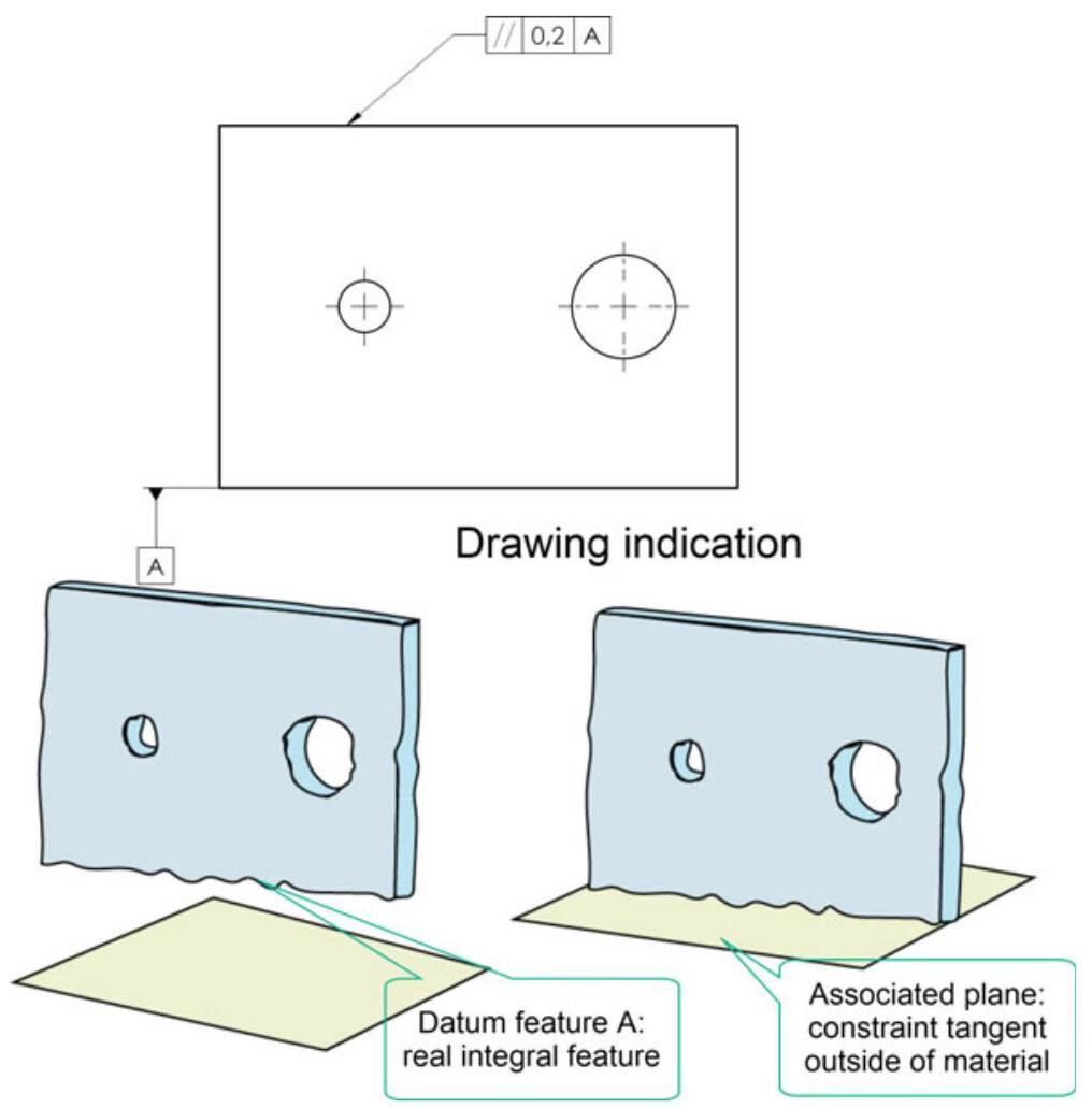
Fig. 6.5 The association process used to obtain a datum: the extracted surface is obtained from the true geometry, through a partition and extraction process, and an ideal tangent plane is associated with such a surface
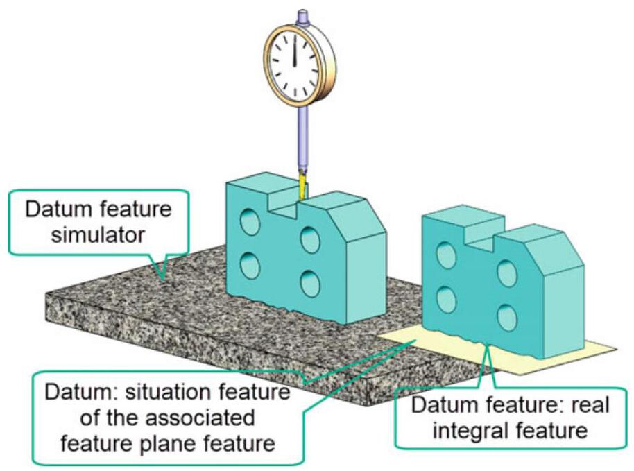
Fig. 6.6 If the datum feature is the flat surface of a workpiece, the associated feature is obtained from a theoretical envelope plane (e.g. a tangent plane) of perfect geometrical form, and it may be approximated from the matching granite plane of the control device
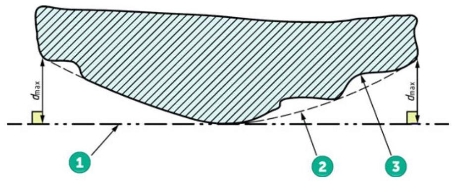
Fig. 6.7 The association method for a planar surface using the minimax criteria. 1. Outside the material tangent plane (datum). 2. Filtered feature. 3. Real integral feature
6.1.2 Datum: Mathematical Concepts
Datums and datum systems are theoretically exact geometric features used together with implicit or explicit theoretically exact dimensions (TED) to locate or orientate the tolerance zones and virtual conditions.
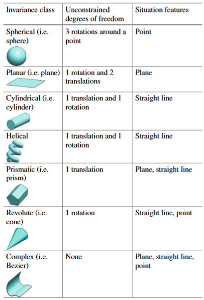
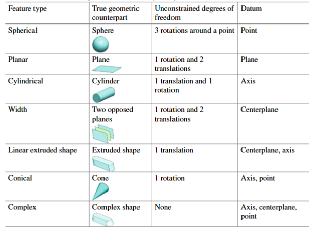
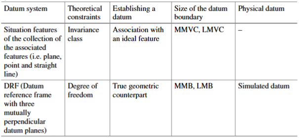
A datum consists of a set of situation features for an ideal feature (feature of perfect form) associated with the identified datum features of a workpiece. Since these ideal features have the task of blocking the degrees of freedom of the tolerance zones, the geometrical type of these associated features should be one of the invariance classes reported in Table 6.1.
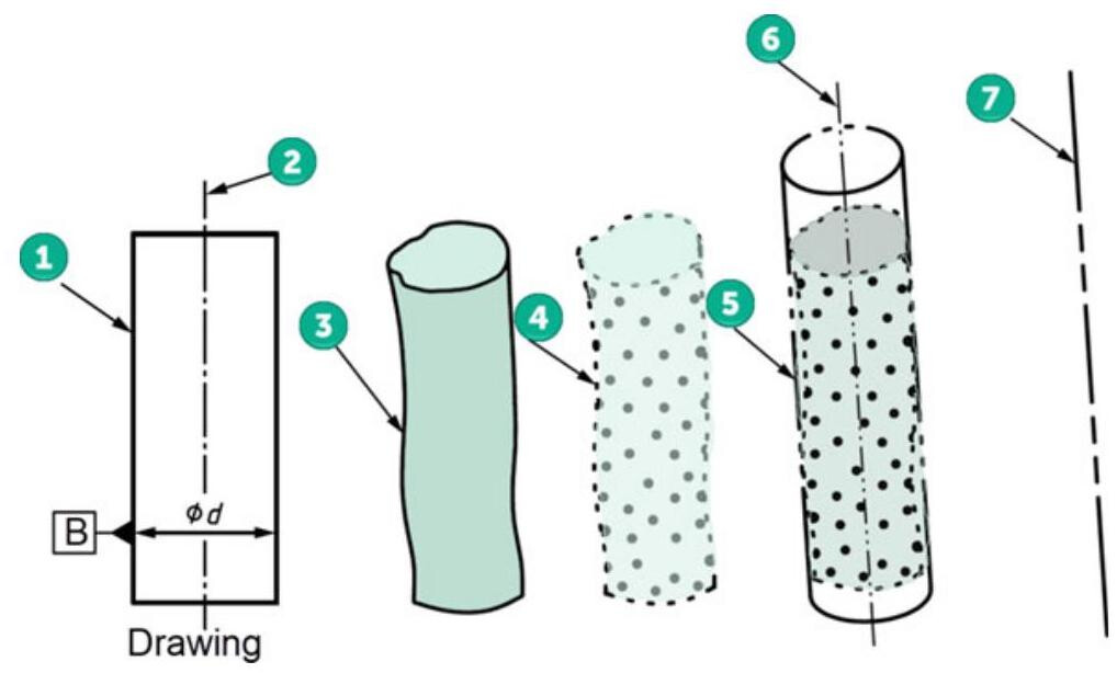
Fig. 6.8 The association and derivation process used to obtain a datum axis from a cylinder: 1. Nominal integral feature. 2. Nominal derived feature. 3. Real integral surface of the workpiece (datum feature). 4. Extracted integral feature; 5. Association with an ideal cylinder. 6. Derived feature (axis of the associated cylinder). 7. Datum (situation feature)
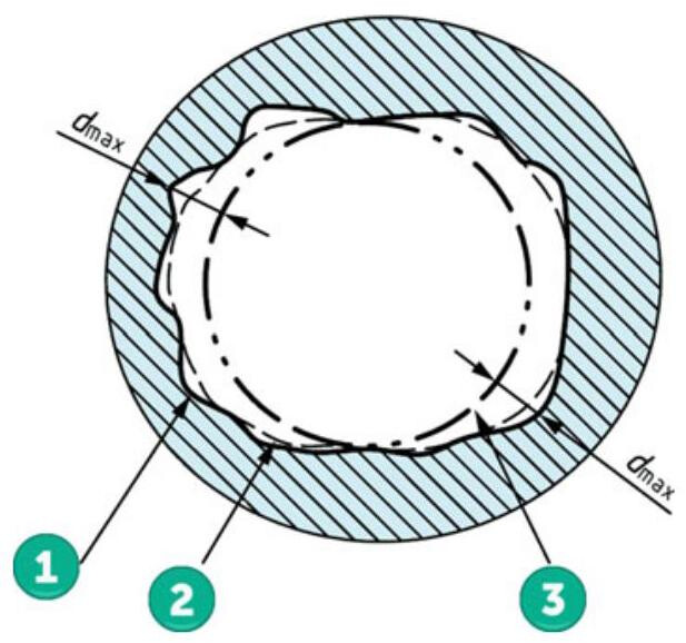
Fig. 6.9 The association method for a cylindrical surface using the minimax criteria. 1. Real integral feature. 2. Filtered feature. 3. Maximum inscribed cylinder
Each feature has 6 degrees of freedom (translations along the x, y, z axes and rotations around the x, y, z axes). The invariance class corresponds to the degrees of freedom (which remain and are not locked). Such a class describes the displacement of the feature (translation, rotation) for which the feature is kept identical in space.
In Table 6.1, all the surfaces are classified into seven classes on the basis of the degrees of freedom for which the surface is invariant. Situation features (point, straight line, plane) are defined for each class of surface.
When a single surface or a collection surface is identified as a datum feature, the invariance degrees for which the surface is invariant should be identified and compared with Table 6.1 in order to determine the set of situation features (point,straight line, plane, or a combination thereof) that constitutes the datum.
Table 6.1 All surfaces are classified into seven classes on the basis of the degrees of freedom for which the surface is invariant
6.2 Indication of Datum Features in Technical Documentation
A datum feature is identified with a capital letter, written within a square, and connected to a triangle that is placed on the feature itself (Fig. 6.10). It is suggested to avoid the use of the letters I, O, Q, X, Y and Z, which could give rise to interpretation problems, while, in the case of complex drawings, it is possible to make use of double letters (AA, BB, etc.).
In the same way as for the tolerance indications, a triangle, with its identification letter, can be located:
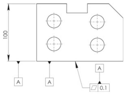
Fig. 6.10 The three ways of indicating a flat surface as a datum feature
(a) on the contour line of the feature surface or on an extension line of the feature outline (but clearly separated from the dimension line) if the datum feature is the surface itself (Fig. 6.11); it is also possible in this case to use a leader line that points directly towards the datum surface (Fig. 6.12).
(b) on an extension of the dimension line of a feature of size when the datum is the feature axis or centerplane of the thus dimensioned part (Fig. 6.13); in this case, for space reasons, it is possible to substitute one of the arrowheads of the measurement line with a datum triangle symbol.
It is necessary to pay particular attention to the correct indication of a datum applied to a feature of size on a drawing: the line of the symbol should coincide with the dimension line of the datum feature, and the indication errors shown in Fig. 6.14 should be avoided.
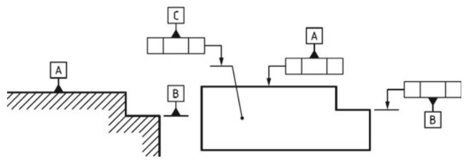
Fig. 6.11 Indications of a datum feature. A triangle does not need to be filled in
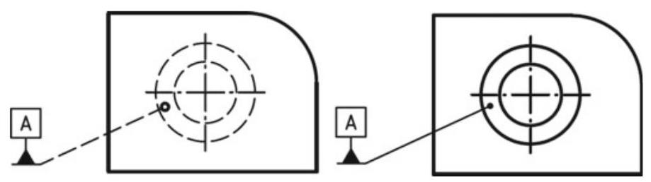
Fig. 6.12 Indications of a datum feature: the dashed leader line indicates that the datum is on the other side (when the considered surface is hidden)
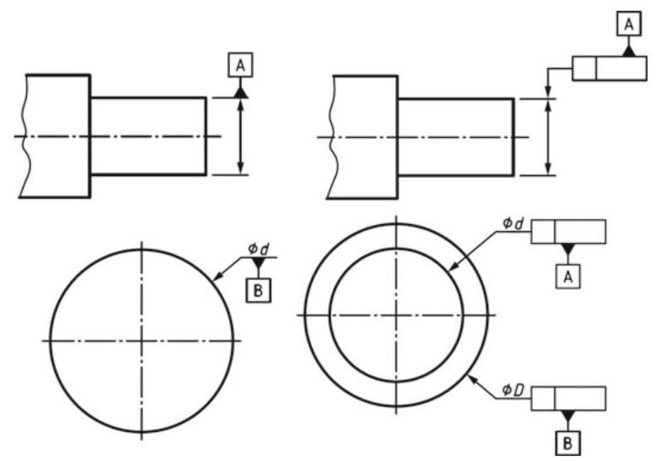
Fig. 6.13 Indication of a datum feature for a feature of size
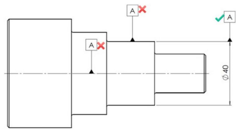
Fig. 6.14 Possible errors in the indications of a datum axis. Cylindrical surfaces should not be used as datums. The symbol line should coincide with the dimension line of the datum feature
In light of all the definitions that have been given so far, does the datum symbol that is utilised in technical drawings indicate a datum or a datum feature (Fig. 6.15)? The symbol obviously indicates a datum feature and not a datum!
6.3 The Datum Systems in ASME Y14.5
The ASME Y14.5 standard makes a clear distinction between the concept of a datum feature, a datum and a datum feature simulator A datum is an abstract geometrical feature (point, axis or plane from which a dimensional measurement is made), which represents the perfect counterpart of a datum feature (e.g. an ideal plane or the axis of the perfect geometrical counterpart).
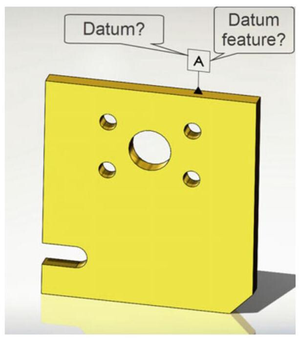
Fig. 6.15 Does the symbol, that is used in technical drawings, indicate a datum or a datum feature? The symbol obviously indicates a datum feature and not a datum
Simulated datums are conceptually perfect (almost physically perfect), and they represent a bridge between the imperfect real world of datum features and the perfect imaginary world of datums. Ultimately, it is opportune to distinguish between the real datum feature of a workpiece (named datum feature) and the datum, that is, the equivalent theoretical datum (plane, axis or centerplane), as simulated by the associated inspection or manufacturing equipment.
The datum system of a tool machine is shown in Fig. 6.16: the production equipment has the task of aligning the features of the workpiece with the datums of the machine (for example, datum feature A is aligned with the clamping machine and datum feature B is made to coincide with the z axis). In short, no datums exist on a workpiece, but they are simulated by the datum feature system of the tool machine.
The true geometric counterpart is the theoretically perfect boundary used to establish a datum from a specified datum feature. True geometric counterparts have a perfect form, and a basic orientation and location relative to other true geometric counterparts for all the datum references in a feature control frame. Furthermore, the true geometric counterparts are adjustable in size, when the datum feature applies an RMB (Regardless Material Boundary), and are fixed at the designated size, when an MMB (Maximum Material Boundary) or an LMB (Least Material Boundary) is specified.
The relationship between the primary datum feature and its true geometric counterpart constrains the degrees of freedom. Table 6.2 shows some examples of degrees of freedom constrained by primary datum features, RMB, in the same way as for the concept of invariance class.
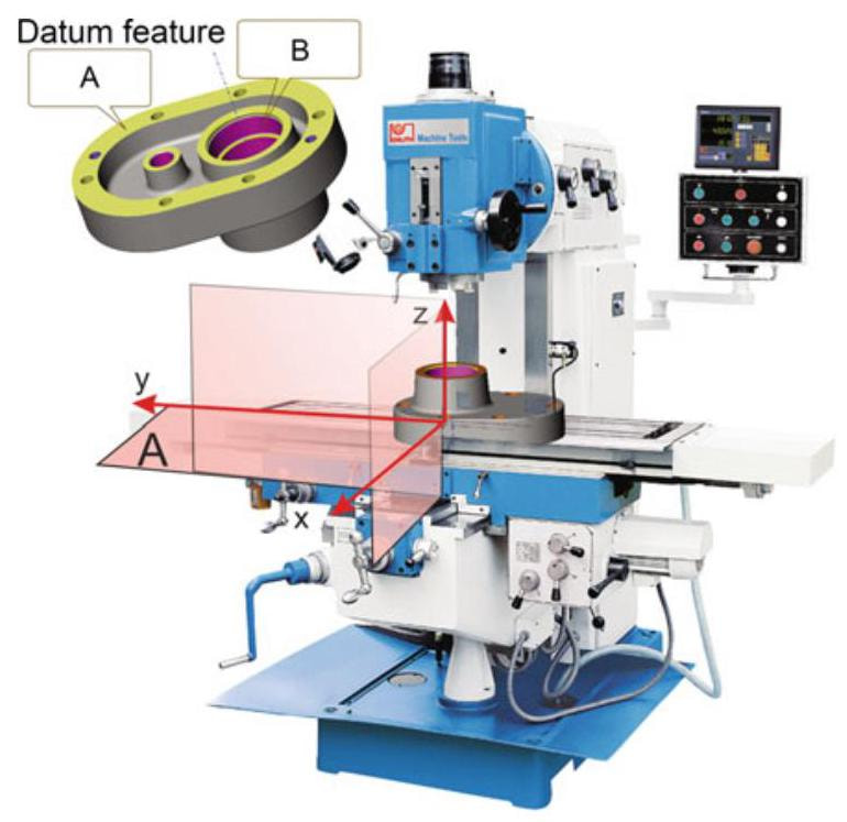
Fig. 6.16 No datums exist on a workpiece, but they are simulated by the datum feature system of the tool machine (physical datum simulators)
Table 6.2 Constrained degrees of freedom for primary datum features
6.3.1 Establishing a Datum
In the case of a datum surface made up of a flat surface of a component, the datum is supplied by a theoretical envelope plane (e.g. a tangent plane, the true geometric counterpart), of perfect geometrical form, and the simulated datum feature is constituted, for example, by the surface plate of the inspection device. As can be seen in Fig. 6.17, it is also possible to define a theoretical envelope plane, of perfect form (true geometric counterpart of a datum feature), on the surface plate; if the workpiece is placed on the surface plate, the two theoretical planes might not coincide because of the irregularities on the surfaces. In spite of this observation, a simulated datum is in fact used as a datum in industrial practice. Such a distinction may appear excessive but, in reality, many errors exist and much confusion arises in defining the datums and in the inspection of the parts with measuring machines.
If, instead, the datum feature is a feature of size, the symbol should be associated with a linear dimension (subject to tolerance) and should therefore be placed directly on the dimension, as shown in Fig. 6.18; in this case, the datum is made up of the axis or centerplane, which is established by an ideal envelope surface.
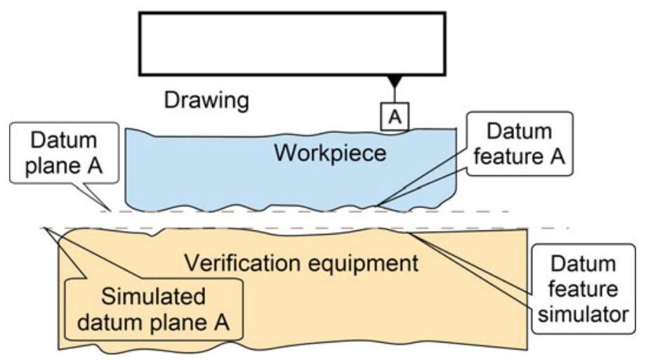
Fig. 6.17 Establishment of a datum plane
Fig. 6.18 Placement of Datum Feature Symbols on Features of Size
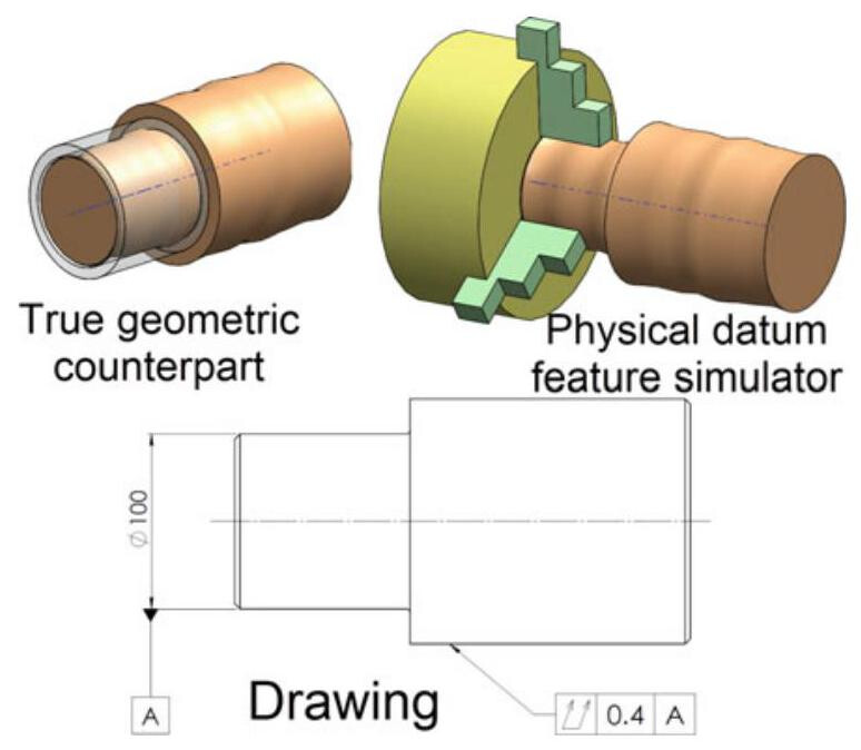
Fig. 6.19 When a cylindrical feature is designated as a datum feature, the datum axis is derived by placing the part in an adjustable gauge (self-centring chuck used as a datum feature simulator)
Figure 6.19 shows the case of a datum made up of the axis of a cylinder; again in this case, it is possible to make a distinction between the axis of the smallest true geometric counterpart and the simulated datum feature, defined as the axis of the feature simulated by the verification gauge. As axes do not exist in the real world, the equivalent theoretical feature is represented, in the case of external features, by the axis of the smallest cylinder restricted by a perfect form. The datum is simulated by the verification device, for example, with a gauge or a self-centring device.
In the case of cylindrical holes, the simulated datum can be established through the use of a cylindrical gauge, with the maximum inscribable diameter, or an expandable chuck; whatever the type of chuck, once inserted into the hole, it does not take on a fixed shape, and it is necessary to regulate it so that any displacements are of the same magnitude in all directions (it is obvious that no modifiers should be applied to the datum).
In short, it is necessary to pay a great deal of attention to the characterisation of the simulated theoretical cylinder (which the ASME standards define as Actual Mating Envelope, AME). In the simplest case, the cylinder is orientated according to the axis of the imperfect hole, but when the axis of the hole is defined on the basis of one or two datums, the simulated cylinder (Related Actual Mating Envelope) is arranged according to the DRF or Datum Reference Frame.
Figure 6.20 further clarifies the meaning of the related and unrelated Actual Mating Envelopes: datum A is a plane,while datum B is the axis of a 34mm cylinder,orientated with an error of 0.05mm with respect to plane A; the 10mm hole is located with respect to datums A and B. The axis of the feature of size is obtained from the smallest restricted orientated cylinder (the unrelated actual mating envelope) and it is useful to verify a perpendicularity error with respect to datum A. The smallest circumscribed cylinder perpendicular to A (the related actual mating envelope) is used to determine the axis of datum B. The derived centerplane is a curve made up of the central points of the transversal section perpendicular to the axis of the feature of size, and it is used to determine the straightness error.
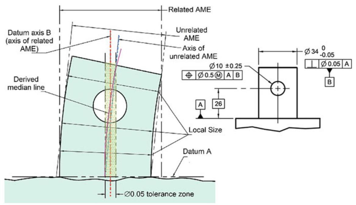
Fig. 6.20 Related and Unrelated AME in the ASME standard
6.3.2 Location of a Workpiece in a Datum Reference Frame
Simulated datums have the purpose of defining a DRF (Datum Reference Frame), that is, the datum system of 3 perpendicular planes that define the origin for the measurements and which allow the workpiece to be blocked during an inspection (Fig. 6.22). In short, the indications of a DRF system supply an immediate description of the orientation and of the location of a workpiece (and of the tolerance zones), thus making the inspection operations univocal and repeatable.
In order to limit the movement of a part so that repeatable measurements can be made, it is necessary to restrict the six degrees of freedom. In fact, each piece that has to be controlled or worked in a datum system has six degrees of freedom (3 linear and 3 rotational, Fig. 6.23). It is possible to show that, in order to eliminate the 6 degrees of freedom, it is necessary to block the workpiece in a datum reference frame with 3 perpendicular planes, named the primary, secondary and tertiary planes, respectively.
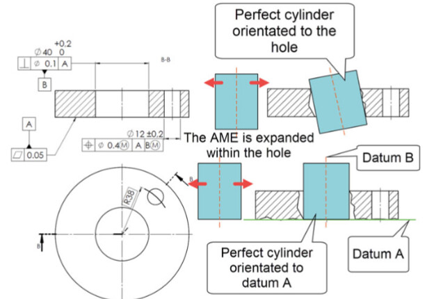
Fig. 6.21 It is necessary to be careful not to confuse the axis of a feature size (obtained through the largest circumscribed cylinder orientated according to the feature), which is useful to control the perpendicularity of a 40mm hole,with the axis of datum B (axis of the largest inscribable cylinder perpendicular to datum A)
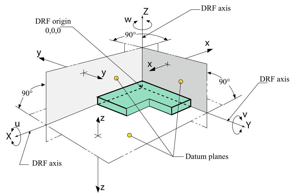
Fig. 6.22 DRF (Datum Reference Frame)
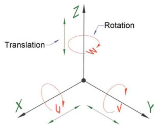
Fig. 6.23 The six degrees of freedom of a workpiece: any movement in the space can be attributed to three possible translations in the direction of the datum axes X, Y and Z and to three rotations, u, v and w, around the same axes
Let us consider the drawing of the component shown in Fig. 6.24, whose holes are located with respect to the three datums A, B and C; in order to conduct a measurement test, datum feature A is put into contact with datum feature simulator A, thus establishing a primary datum with at least three points of contact, and eliminating a degree of linear freedom Z and two rotational degrees of freedom, that is, u and v (Fig. 6.25).
Datum feature B is then put in contact with datum feature simulator B, and in this way secondary datum B is established, with a minimum of two points of contact and elimination of a linear degree, X, and a rotational one w (Fig. 6.26). Finally, tertiary datum C is defined with just a single point of contact and the last degree of freedom Y is eliminated by putting datum feature C in contact with its simulator (Fig. 6.27).
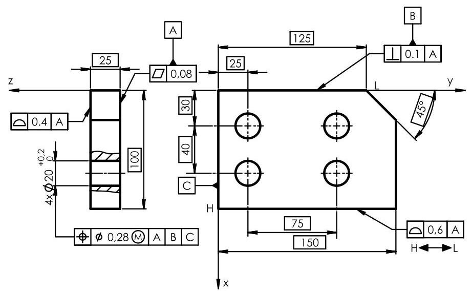
Fig. 6.24 In order to make the identification of a datum reference frame clearer, the ASME Y14.5 standard introduced the possibility of identifying the axes of the datum system on a drawing in order to offer an immediate description of the orientation and location of a workpiece (and of the relative tolerance zone), thus making the measurement test operations univocal and repeatable
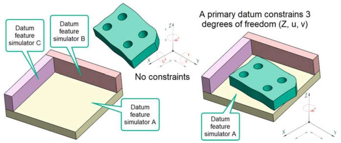
Fig. 6.25 Datum feature A of the component is put in contact with the datum feature simulator, and in this way a primary datum is established, with a minimum of three contact points and elimination of a degree of freedom Z and two rotational ones,that is,u and v. The X,Y and w degrees of freedom still have to be constrained
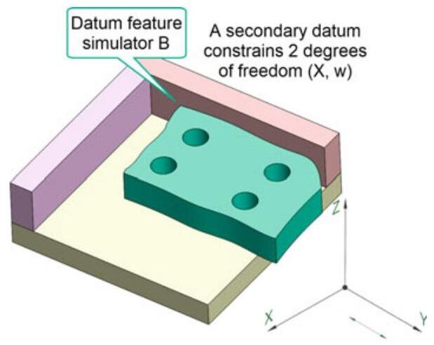
Fig. 6.26 Subsequently, datum feature B is put in contact with datum feature simulator B, and in this way the secondary datum is established, with a minimum of two contact points and elimination of a linear degree, X ,and a rotational one w. The translation along Y still has to be constrained
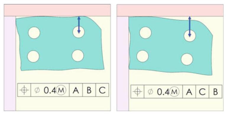
Fig. 6.28 The order of the datums in the tolerance frame indicates the sequence of the inspection operations; as can be seen, the location dimension of the hole changes according to the datum plane on which the workpiece is placed
It is necessary to pay particular attention to the order of the datum sequence as it influences the result of an inspection. In fact, if the inspection procedure of the workpiece in Fig. 6.28 is considered, it can be noted that, as the location tolerances have been indicated in the datum order A, B and C in the frame, the inspection procedure should be conducted after locating the workpiece in the datum system according to the exact same order. A change in this order (i.e. A, C, B) would influence the measurement test, as can be seen in the same figure.
6.3.3 Selection of Datum Features
The starting point for a correct dimensioning is the identification of a datum reference frame with 3 perpendicular planes (DRF), and in this way functioning and mating of the parts are guaranteed. As previously mentioned, it is erroneous to think that the datums should only be established in the manufacturing design phase on the basis of the requirements of the various operations. Datums should in fact be selected on the basis of the functional requirements of a part in order to allow the functional relationships to be communicated on the drawing. The datums should instead always be established on the basis of the functional requirements because, if the datums are chosen on the basis of the technological location of the workpieces, the tolerance available for manufacturing may be reduced.
The choice of the datum features should obviously be considered in function of the assembly requirements of the parts, and their sequence very often reproduces the logical assembly sequence. The case shown in Fig. 6.29 can be considered as an example: the part with 2 holes should be mated to the plate by means of two fixed fasteners. The logical sequence that allows an appropriate choice of the three datums to be made is:
-
identification of the feature that orientates the workpiece in the assembly, in order to establish the primary datum; in Fig. 6.30, the feature that orientates the workpiece is constituted by mating surface A.
-
Identification of the feature that locates the workpiece in the assembly, in order to establish the secondary datum; datum feature B that locates the workpiece is represented by the axis of the two cylindrical features.
-
Identification of the feature that blocks the workpiece in the assembly, in order to establish the tertiary datum. Finally, tertiary datum C that blocks the workpiece, which is constituted by the milled surface of the component and of the corresponding surface of the plate, is added.
-
Qualification of the datum features through the application, orientation and location of opportune form tolerances.
-
Location of all the geometrical features with reference to the datum features, while utilising the profile tolerances to locate the surfaces.
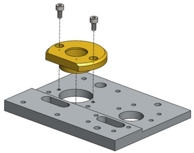
Fig. 6.29 Choice of the functional datums for a mating with fixed fasteners
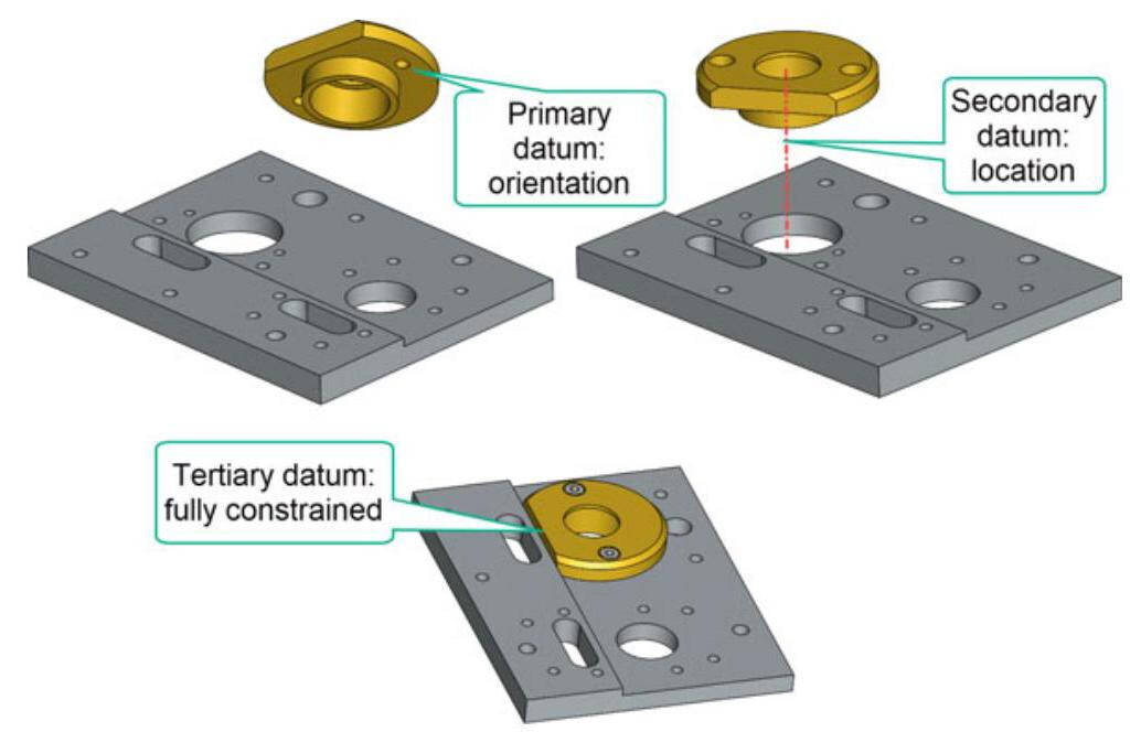
Fig. 6.30 The feature that is used to orientate the workpiece is made up of mating surface A (which is defined as the primary datum), while the feature that is considered to locate it is the axis of the two cylindrical features (which is defined as a secondary datum). Finally, the tertiary datum that blocks the workpiece, which is constituted by the milled surface of the component and of the corresponding surface of the plate, is added
The complete dimensioning of the upper component is reported in the ASME drawing in Fig. 6.31. The dimensioning of the lower plate is obtained by following the same previously outlined rules.
However, it is not always necessary to use three datums. The case shown in Fig. 6.32 can be considered as an example: the cover with the holes should be mated with the tank through fixed fasteners; the feature that orientates the workpiece is constituted by mating surface A (which is defined as the primary datum), while the feature that locates it is represented by the axis of the cylindrical part (which is defined as the secondary datum). When the axis of a cylinder is used as the datum feature, it is necessary to imagine using two perpendicular planes, whose intersection determines the datum axis, and which can rotate freely around the same axis (Fig. 6.33).
If the assembly of the cover takes place as in Fig. 6.34, that is, the tongue must be mated with the relative groove, three datums are required, that is, it is necessary to add the tertiary datum that blocks the workpiece and which is constituted by the centerplane of the groove.
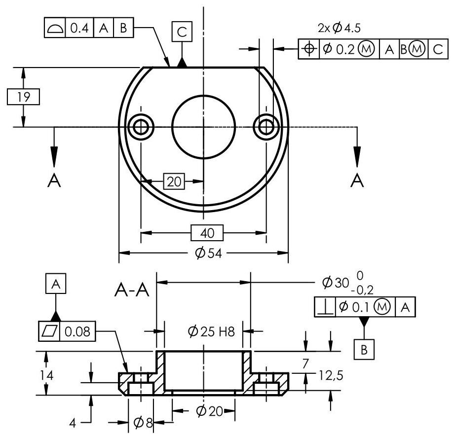
Fig. 6.31 Complete dimensioning of a component with the 3 established functional datums. The primary datum is qualified with a planarity tolerance and the secondary one with a perpendicularity tolerance. Finally, the two holes in the plate are located with a location tolerance with respect to the three established datums

Fig. 6.32 Selection of the primary datum (used to orientate) and of the secondary datum (used to locate)
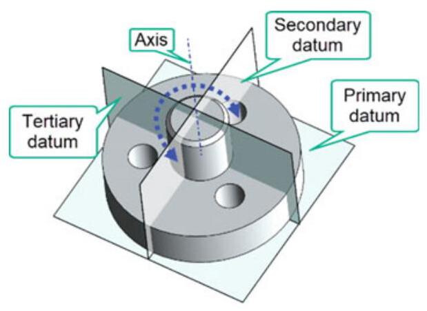
Fig. 6.33 The axis of a cylinder that is used as a datum feature is associated with two imaginary perpendicular planes, whose intersection determines the datum axis, which can rotate freely around the same axis
In this case, the two imaginary planes can no longer rotate and are constrained in a precise location (Fig. 6.35). Table 6.3 summarises the main differences between the ISO and ASME standards pertaining to the specification of a datum.
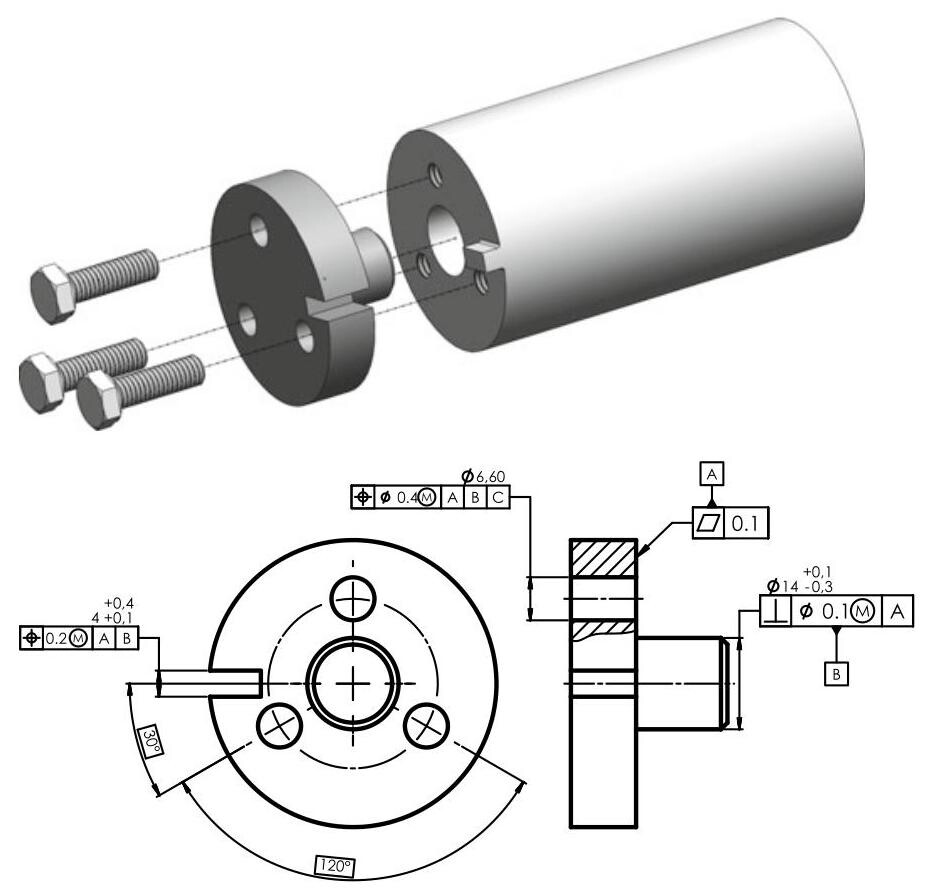
Fig. 6.34 Selection of the primary datum (used to orientate), of the secondary datum (used to locate) and of the tertiary datum (used to block)
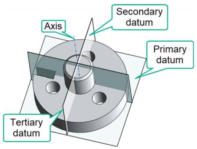
Fig. 6.35 The second datum is constituted by an axis and the third by a centerplane: the two imaginary planes can no longer rotate and are constrained in a precise location
6.4 Examples of Datum Systems in the ISO Standards
In an ISO standard, a datum system is a set of two or three situation features established in a specific order from two or more datum features. A primary datum is a datum that is not influenced by any constraints from other datums. A secondary
Table 6.3 The main differences between the ISO and ASME standards pertaining to the specification of a datum
datum is a datum, in a datum system, that is influenced by a primary datum orientation constraint in the datum system. A tertiary datum is a datum, in a datum system, that is influenced by constraints from the primary datum and the secondary datum in the datum system. A datum system is constituted by an ordered sequence of two or three datums. This order defines the orientation constraints that should be followed for the association operation: the primary datum imposes orientation constraints on the secondary datum and tertiary datum; the secondary datum imposes orientation constraints on the tertiary datum.
6.4.1 Datum System with Three Single Datums
6.4.1.1 Three Perpendicular Planes
The datum system is composed of three single datums with orientation constraints (perpendicularity) between them (Fig. 6.36). The datums are used together sequentially, in a given order, to orient and locate the tolerance zone relative to a plane, one of its straight lines and one of its points (equivalent to three planes). These are the situation features of the collection of the three associated planes.
The primary datum is an associated plane; the secondary datum is an associated plane that respects the orientation constraint of the primary single datum; the tertiary datum is an associated plane that first respects the orientation constraint from the primary datum and then the one from the secondary datum (Fig. 6.37). The situation features are a plane (corresponding to the primary datum), a straight line (the intersection between this plane and the plane corresponding to the secondary datum) and a point (the intersection between the straight line of the secondary datum and the plane corresponding to the tertiary datum).
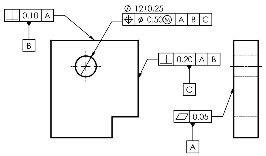
Fig. 6.36 Datum system with three perpendicular planes
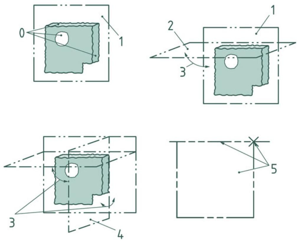
Fig. 6.37 Establishing a datum system from three perpendicular planes: 0. Datum feature: real integral features. 1. The plane associated with the primary datum feature identified by datum letter A. 2. The associated plane (secondary datum) identified by datum letter B, with an orientation constraint from primary datum. 3. The perpendicularity constraint. 4. The associated plane (tertiary datum) identified by datum letter C, with orientation constraints from the primary datum and secondary datum. 5. The datum system: plane (primary datum), straight line (intersection between the primary and secondary datums) and point (intersection of the three datums)
6.4.1.2 A Plane and Two Perpendicular Cylinders
In this case, a planar surface and two perpendicular cylinders are used to establish a datum system by considering a variable size of the cylinders and a perpendicularity constraint between the axis of the associated cylinders and the associated plane (Fig. 6.38).
The datum system is characterised by the situation feature of the collection of a plane and two perpendicular cylinders, with a constraint location between them. The primary datum in the datum system is an associated plane; the secondary datum is an associated cylinder, which respects the orientation constraint from the primary single datum; the third associated feature is an associated cylinder with a perpendicularity constraint from the primary datum and a location constraint from the secondary datum (Fig. 6.39). The situation features are a plane (first associated feature), a point (intersection between the plane and the axis of the second associated feature) and a straight line (intersection between the associated plane and the plane containing the two axes, Fig. 6.40).
6.5 Type of Datum
6.5.1 Centerplanes (Width-Type Features of Size)
The design intent of the drawing shown in Fig. 6.41 is to achieve symmetry of the median plane of the internal slot with respect to the median plane of the external element. In this case, the real integral surface resulting from the collection of two nominally parallel planar surfaces, which is a feature of size, is used to establish a datum by considering the size variable.
The two real integral surfaces of the workpiece indicated in Fig. 6.42 are obtained after partition/extraction/collection and constitute a feature of size of variable size.
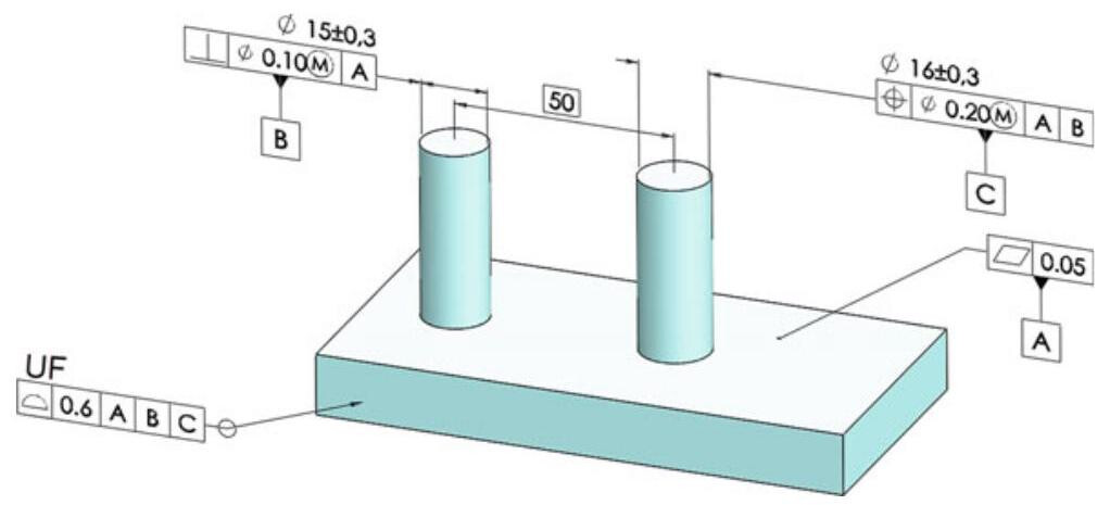
Fig. 6.38 Datum system taken from a plane and two cylinders
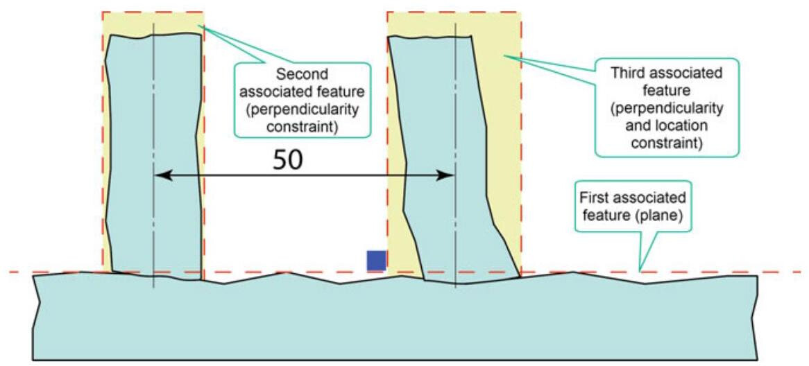
Fig. 6.39 The primary datum in the datum system is an associated plane; the secondary datum is an associated cylinder that respects the orientation constraint from the primary single datum; the third associated feature is an associated cylinder with a perpendicularity constraint from the primary datum and a location constraint from the secondary datum
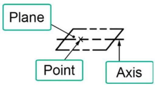
Fig. 6.40 The situation features are a plane (first associated feature), a point (intersection between the plane and the axis of the second associated feature) and a straight line (intersection between the associated plane and the plane containing the two axes
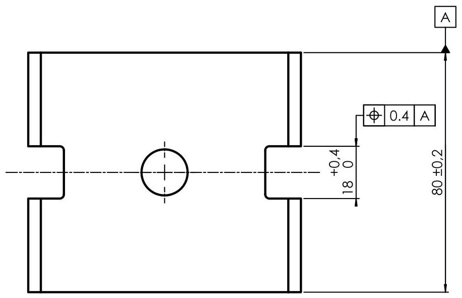
Fig. 6.41 The design intent is the symmetry of the median plane of the internal slot with respect to the median plane of the external element
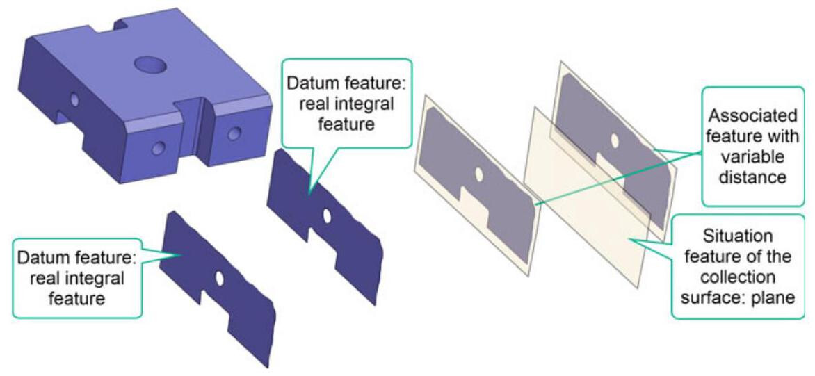
Fig. 6.42 Establishing a single datum from a feature of size (two parallel opposite planes)
The single datum is characterised by the situation feature obtained from the collection of two parallel planes associated with the real integral features used to establish the single datum.
The association is made with an internal parallelism orientation constraint (the distance between the two planes is variable). The invariance class of the collection of nominal surfaces is planar and the situation feature is a plane (the median plane of the two associated planes).
In the ASME standard, the central datum plane of an external feature is the symmetry plane between two parallel planes which, at the minimum distance, are in contact with the corresponding surfaces of the workpiece (Fig. 6.43); vice versus, the central datum plane for internal features is constituted by a symmetry plane between two parallel planes which, at the maximum distance, are in contact with the corresponding surfaces of the workpiece (Fig. 6.45). Figure 6.44 shows a simulation (according to the ASME standards) of the centerplane assumed as the datum of the component shown in Fig. 6.41.
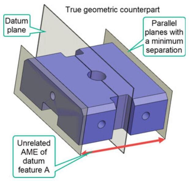
Fig. 6.43 ASME standard: the central datum plane of an external feature is the symmetry plane between two parallel planes which, at the minimum distance, are in contact with the corresponding surfaces of the workpiece
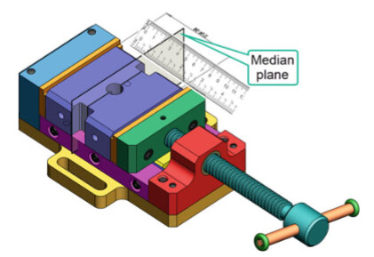
Fig. 6.44 Physical datum feature simulator in ASME: Datum centerplane of a component. The simulation of the datum is obtained with the median plane of the two parallel surfaces of the vise
clamps
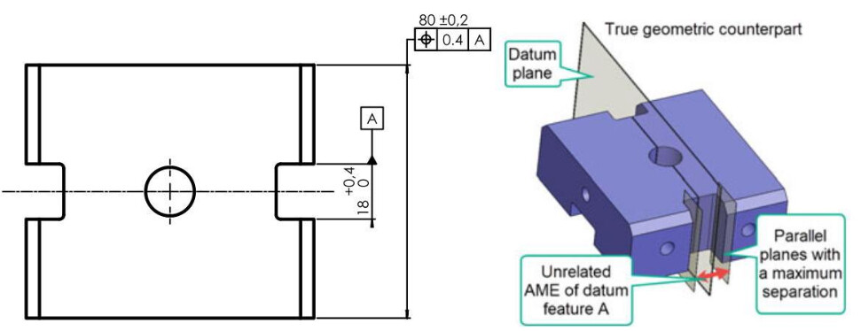
Fig. 6.45 The central datum plane for internal features is constituted by a symmetry plane between two parallel planes which, at the maximum distance, are in contact with the corresponding surfaces of the workpiece
It is necessary to pay particular attention to the location of the datum feature symbol (Fig. 6.46). Placing the symbol on the extension of the dimensioning line indicates a feature of size, that is, the centerplane of the feature, otherwise, the indicated datum feature is the lateral plane.
6.5.2 Common Datum
In some cases, the datum is established by utilising two or more datum features in a simultaneous way until a common datum is defined, that is, a datum established from two or more datum features after simultaneous associations without any specific order, but with interrelated constraints.
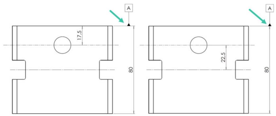
Fig. 6.46 It is necessary to pay particular attention to the location of the datum feature symbol. Placing the symbol on the extension of the dimensioning line indicates the centerplane of the feature, otherwise the indicated datum feature is the lateral plane
The design intent of the drawing shown in Fig. 6.47 is to simultaneously use two integral, nominally cylindrical and coaxial surfaces, which are features of size, to establish a datum, by considering their sizes variable and the orientation constraint (parallelism) and location constraint (coaxiality). The common datum (axis) is used to orient and locate the tolerance zone of the run-out control. This axis is the situation feature of the collection of the two associated cylinders.
The common datum in Fig. 6.48 is characterised by the situation feature of the collection of two coaxial cylinders associated with the real integral features used to establish the common datum. The association is made with internal constraints: zero distance and parallel (coaxial). The invariance class of the collection of nominal surfaces is cylindrical, and the situation feature is the common axis of the two cylinders.
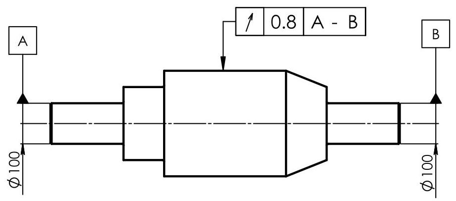
Fig. 6.47 A common datum is established simultaneously with two integral cylindrical and coaxial surfaces. The common datum is used to orient and locate the tolerance zone of the run-out control. It is important to underline that the two letters in the frame indicate that the datum features are separated by a hyphen as they refer to a single datum
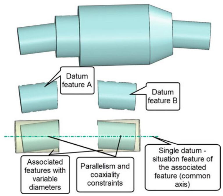
Fig. 6.48 Establishing a common datum from two coaxial cylinders
The common datum axis A-B in the ASME standard is the axis of the true geometric counterpart (smallest pair of coaxial circumscribed cylinders). The physical datum simulator of the A-B axis is a couple of coaxial centring devices (Fig. 6.49).
The design intent of the drawing shown in Fig. 6.50 is the simultaneous use of two integral, nominally planar surfaces constrained to be coplanar, which are not features of size, to establish a datum. The datum is used to orient the parallelism tolerance zone relative to this plane (the situation feature of the collection of the two associated planes).
In this case the real integral surfaces are obtained after partition/extraction and collection, and the common datum is characterised by the situation feature of the collection of two coplanar planes associated with the real integral features used to establish the common datum (Fig. 6.51). The association is made with coplanar internal constraints (i.e. zero distance and parallel). The invariance class of the collection of nominal surfaces is planar and the situation feature is a plane.
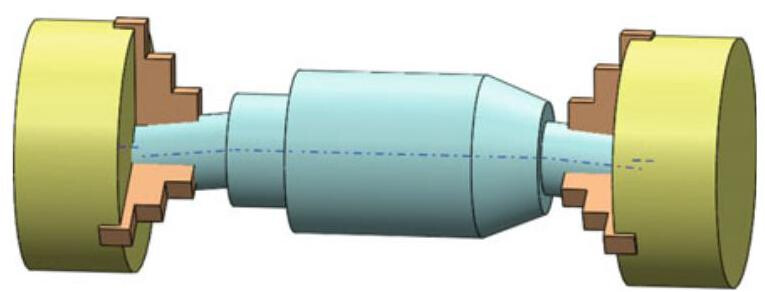
Fig. 6.49 Physical datum feature simulator of the common datum axis as in the ASME standard. The simulation of the datum is obtained with two coaxial centring devices
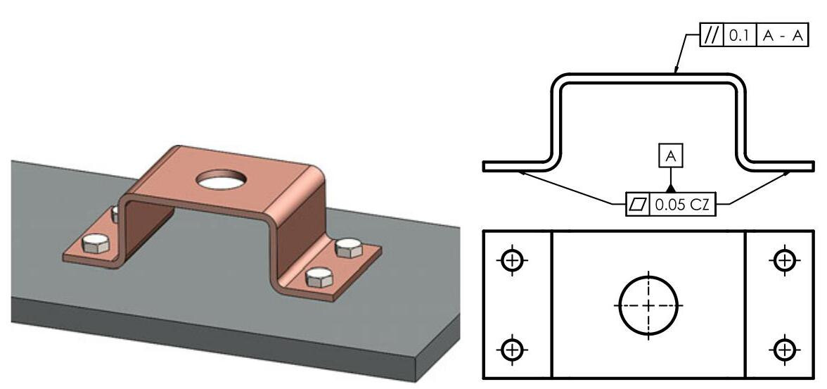
Fig. 6.50 An example of two coplanar surfaces used to establish a common datum A-A
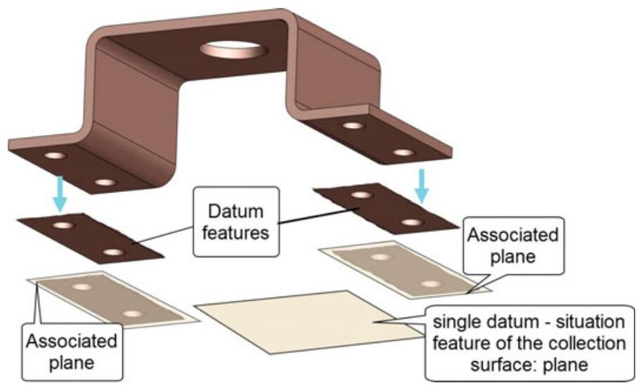
Fig. 6.51 Establishing a common datum from two coplanar planes
6.5.2.1 Pattern of Holes as a Common Datum
A pattern of holes can be chosen as a common datum to simultaneously establish a datum, taking into consideration the size, orientation, and location of the associated cylinders. Two parallel holes are used as a common datum in Fig. 6.52. In this case, the two integral cylindrical and parallel surfaces, which are features of size, are used simultaneously to establish a datum by considering the size of the cylinders variable and the orientation constraint (parallelism) and location constraint (76mm) between the two axes. The situation feature is made up of a plane that passes through the two axes of the holes and the median straight line of the axes of the two associated cylinders (Fig. 6.53).
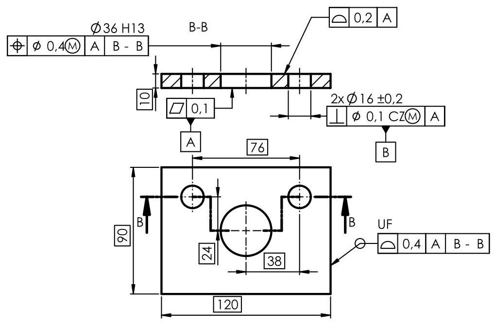
Fig. 6.52 The two 16mm holes are used as a common datum. It should be noted that,in this case, two datums are sufficient to eliminate all the degrees of freedom, as the two “hole axis” datums are constrained as far as the orientation (parallelism) and location are concerned
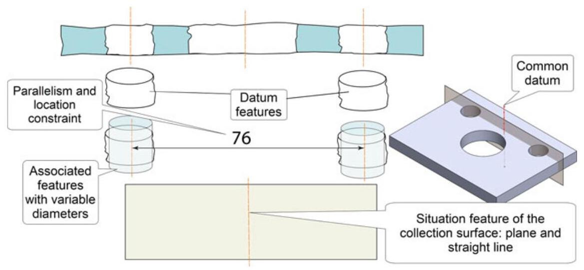
Fig. 6.53 Establishing a common datum from two parallel cylinders: the situation features are the plane containing the two axes and the median straight line of the axes of the two associated cylinders
The same component is shown in Fig. 6.54, where the common datum is indicated with a DV (distance variable) modifier, which allows only the orientation (parallelism), and not the distance between the two holes, to be constrained.
The design intent of the drawing in Fig. 6.55 is to simultaneously use four integral, nominally identical and cylindrical surfaces, which are features of size, together with parallel axes to establish a datum by considering the size of cylinders variable and the orientation constraints (parallelism) and location constraints 76×48mm .
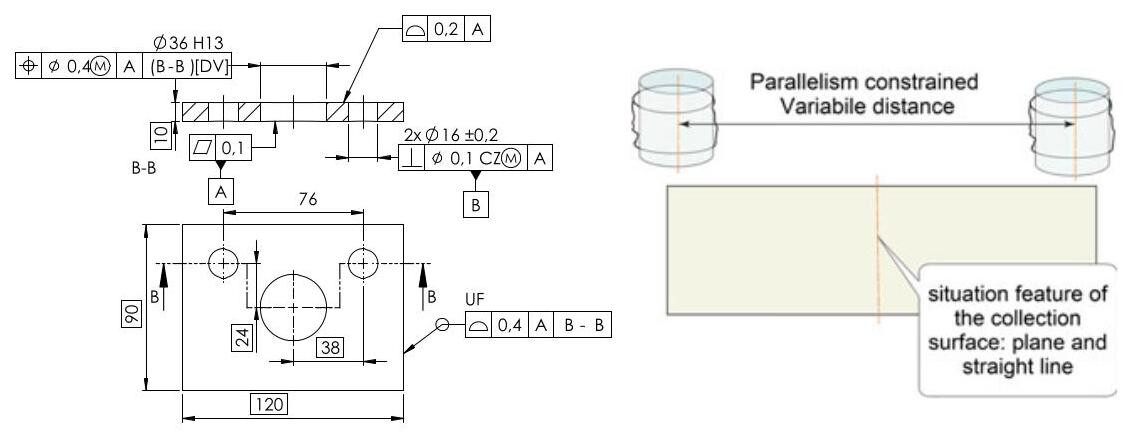
Fig. 6.54 The common datum is indicated with a DV (distance variable) modifier. The two 16mm holes simultaneously establish a common datum, but the axes are only constrained in orientation (parallelism) and not in location. The verification is obviously conducted with a different piece of equipment from the previous case
Fig. 6.55 A pattern of 4 holes can be utilised as a common datum, by associating cylinders of variable diameter, in order to establish a datum reference frame. The datum axes are constrained in orientation (parallelism) and location by the theoretically exact dimensions (76 and 48mm ). It should be noted that, again in this case, two datums are sufficient to eliminate all the degrees of freedom
The datum axes in Fig. 6.56, are constrained, as far as the orientation (parallelism) and location are concerned, by the theoretically exact dimensions of the distances (76 and 48mm ) and a couple of identical capital letters are used for indication purpose
Four cylinders that are simultaneously constrained in orientation and location are associated with the true integral features. As in the previous case, the final common datum is defined from the central axis of the pattern and from a plane that passes through the axis of one of the associated cylinders.
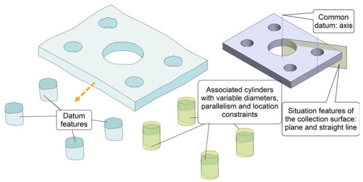
Fig. 6.56 Four cylinders that are simultaneously constrained in orientation and location are associated with the true integral features. As in the previous case, the final common datum is defined by the central axis of the pattern and by a plane that passes through the axis of one of the associated cylinders
6.5.3 Conical Surfaces as Datum Features
When a cone is defined as a datum feature, the resulting datum is made up of a line (axis) and a point (vertex of the cone, as in Fig. 6.57, or a particular point along the axis, which is defined by the position at which the diameter of the section is specified, as in Fig. 6.58). An ideal cone, with the same angular opening, is associated with the real integral surface of the cone, whose axis defines the common datum which, together with the point, eliminates 5 degrees of freedom (Fig. 6.59).
The design intent of the drawing shown in the Fig. 6.60 is to use the integral, nominally conical surface, which is a feature of size, to establish a datum by considering its size fixed. Only the datum is used to orient and locate the tolerance zone relative to an axis (coaxiality). In this case, this axis is the situation feature of the associated cone, and the point is not involved in the location of the tolerance zone.
Figure 6.61 shows an ASME drawing in which conical primary datum feature A constrains five degrees of freedom, including translation in Z. In this case, the YZ and ZX planes may rotate because rotation w is not constrained. The datum reference frame used to locate the 10mm
diameter hole originates at the apex of the conical true geometric counterpart. When orthographic views are used, the rectangular coordinate axes should be labelled in at least two views on the drawing.
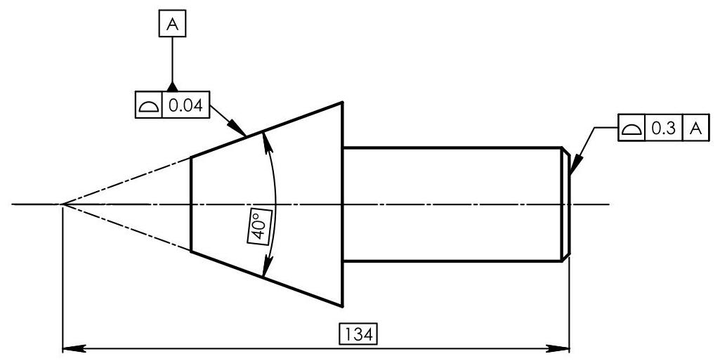
Fig. 6.57 The design intent of the drawing is to use the integral, nominally conical surface, which is a feature of size, to establish a datum by considering its size fixed. Only the datum is used to orient and locate the profile tolerance zone relative to its situation features, which are the axis of the associated cone and a point along this axis
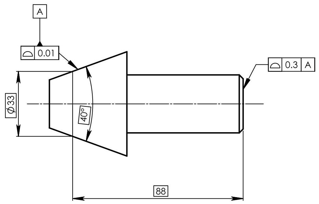
Fig. 6.58 The design intent is the same as is in the previous figure, but this time the situation features are the axis of the associated cone and a particular point along the axis, defined by the location at which the section diameter is specified
6.6 Datum Features Referenced at MMR and LMR (Size Datum)
As the dimension of a feature of size may vary from the maximum to the least material, when it is used as a datum feature, it is necessary to specify whether it is used for the maximum material conditions (defined as MMVC (Maximum Material Virtual Condition), LMVC (Least Material Virtual Condition), or in any intermediate conditions (default)).
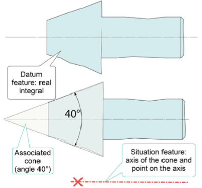
Fig. 6.59 The real integral surface is obtained after partition/extraction. The datum is characterised by the situation features of the cone associated with the real integral feature without external constraints. The invariance class of the nominal surface is revolute and the situation features are the axis of the cone and a particular point along this axis (vertex or defined by the location)
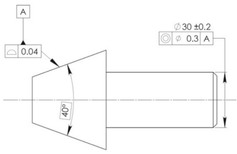
Fig. 6.60 Only the datum is used to orient and locate the tolerance zone relative to an axis (coaxiality). In this case, this axis is the situation feature of the associated cone, and the point is not involved in the location of the tolerance zone
When there are no modifiers, default conditions are assumed, and in this case, as has been observed so far, it is possible to derive the datum from the associated perfect geometry (axis or centerplane). On the other hand, if there is a material modifier, the datum is the axis or centerplane of the virtual conditions, and therefore has a fixed size.
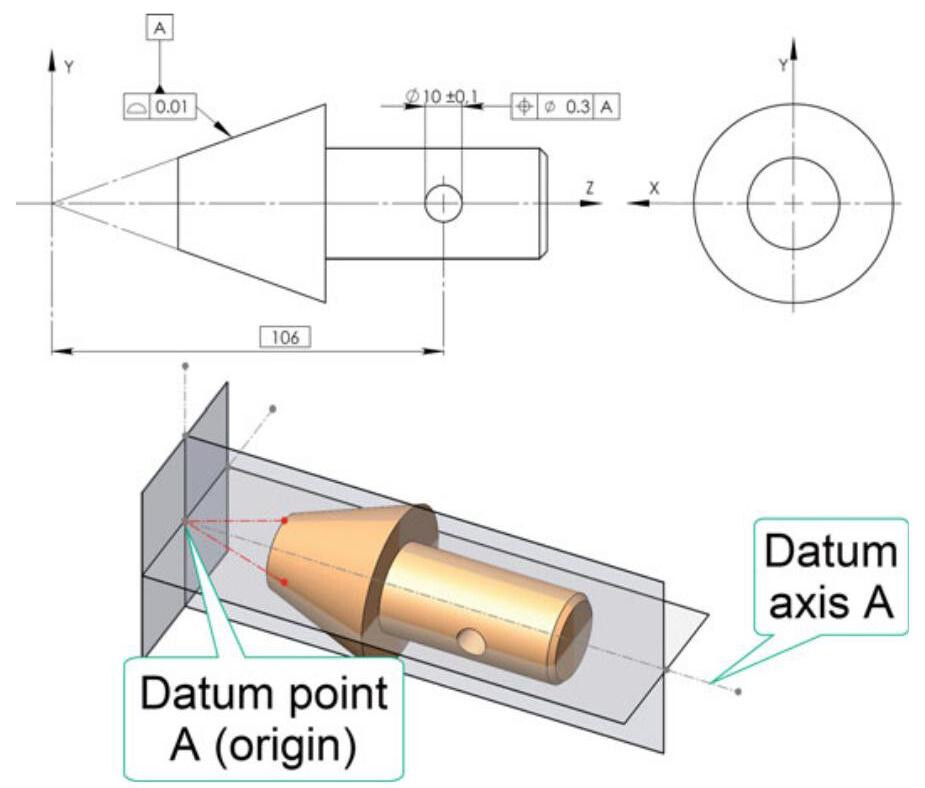
Fig. 6.61 ASME drawing: conical datum feature referenced to constrain five degrees of freedom. When orthographic views are used, the rectangular coordinate axes should be labelled in at least two views on the drawing
The case of the dimensioning of the plate in Fig. 6.62 should be considered: the 16mm central hole is referenced with respect to a datum reference frame constituted by three planes, that is, A, B and C, and in turn constitutes a datum feature D (Diameter 16mm ) of the two 8mm holes that are located with respect to the A,D and C datum system.
Since a maximum material modifier appears next to the indications of datum feature D, the extracted feature of the datum feature should not violate its MMVCs, which is a cylinder an MMVS diameter:
The axis of the MMVC virtual condition is theoretically exactly oriented (perpendicular) to datum A,and in the theoretically exact location ( 28mm ) relative to datums B and C (Fig. 6.63).
Figure 6.64 shows the case of an external datum feature B ( 28mm ),qualified by means of perpendicularity with respect to primary datum A. The extracted feature of the datum feature B should not violate the maximum material virtual condition
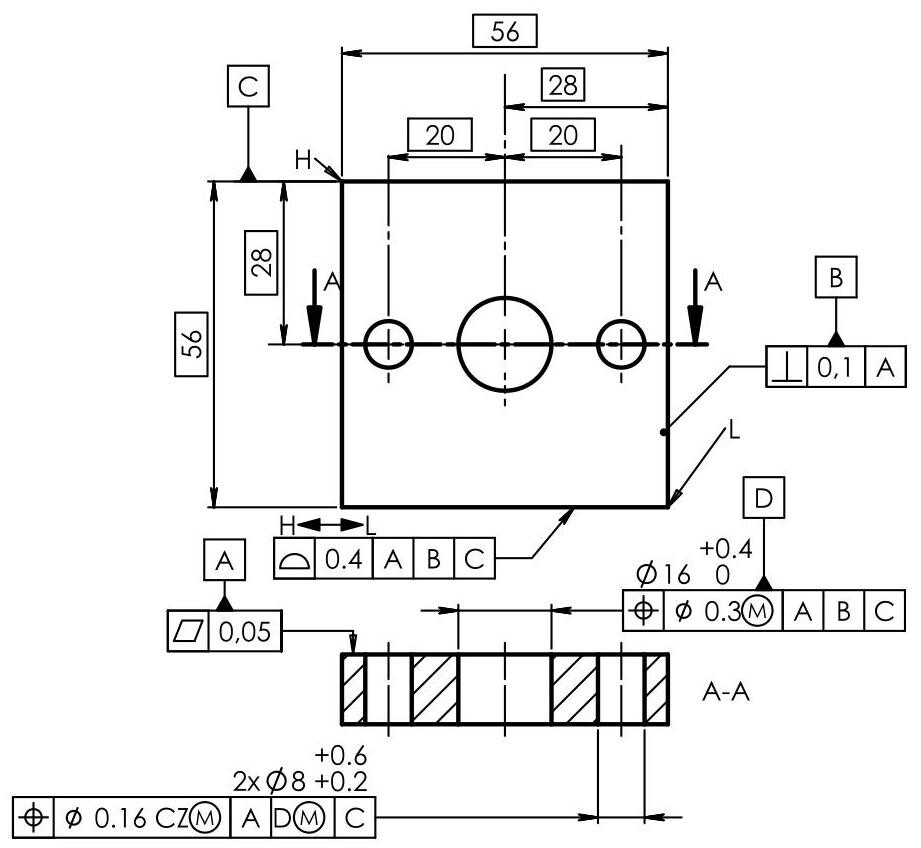
Fig. 6.62 The 16mm central hole is referenced with respect to an A,B and C datum system,which in turn constitutes a datum feature D of the two 8mm holes that are located with respect to the A,D and C datum system. A maximum material modifier appears next to the indication of datum feature D
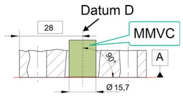
Fig. 6.63 The extracted feature of datum feature D should not violate its MMVC ( 15.7mm ),The axis of the MMVC virtual condition is theoretically exactly oriented (perpendicular) to datum A, and in the theoretically exact location (28mm) relative to datums B and C
MMVC 28.2mm ,which is obtained by summing the geometrical tolerance with the maximum material dimension, MMS. At the same time, the extracted feature of the toleranced internal feature should not violate the MMVC (MMVS 9.6mm ) oriented with respect to datum A and located at 0mm from the axis of the MMVC of datum feature B.
Apart from being applied to axes, a maximum material modifier or a least material modifier can also be applied to centerplanes. In fact, in the case of the drawing in Fig. 6.65, by indicating the maximum material modifier next to datum feature A, the datum becomes the centerplane of a block under MMVC conditions (in this case, coinciding with the maximum material dimensions of the slot, that is, 18 mm). The extracted feature of the slot should not violate the MMVC.
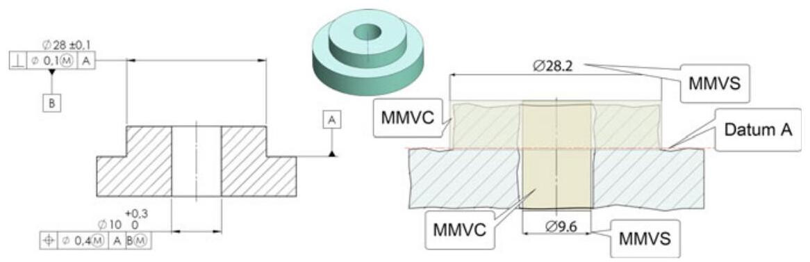
Fig. 6.64 The control of the central hole takes place through an orientation with respect to datum A and coaxially with respect to datum B. The extracted feature of the toleranced internal feature should not violate the MMVC (MMVS 9.6mm ) and the extracted feature of datum feature B should not violate the MMVC (MMVS 28.2mm )
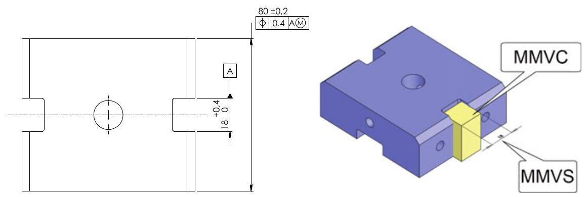
Fig. 6.65 By placing the maximum material modifier next to the indications of datum feature A, the datum becomes the median plane of a block under MMVC conditions (in this case, coinciding with the maximum material dimensions of the slot,that is, 18mm )
Analogously, in the case of external features (Fig. 6.66), the datum becomes the centerplane of two symmetrical blocks, at the distance from the MMVC conditions, that should not be violated (in this case, coinciding with the maximum material dimensions of the datum, that is, 80.2 mm).
It is possible to apply the maximum, or the least material modifiers, to a common datum constituted by a pattern of holes, as shown in Fig. 6.67. In this case, the virtual condition is defined by 4 cylinders perpendicular to datum A, constrained in orientation and spacing and of constant dimensions (15.8-0.1=15.7mm). The extracted features of the four tolerance features should not violate the MMVC, which has a diameter MMVS 15.7mm, Moreover,the four datum features are theoretically exactly oriented to datum A and in the theoretically exact location relative to each other \left( {{76} \times {48}\mathrm{\;{mm}}}\right) , The extracted feature of the central \varnothing {16}\mathrm{\;{mm}} , hole should not violate the MMVC,which has a \varnothing {35},6\mathrm{\;{mm}} diameter.
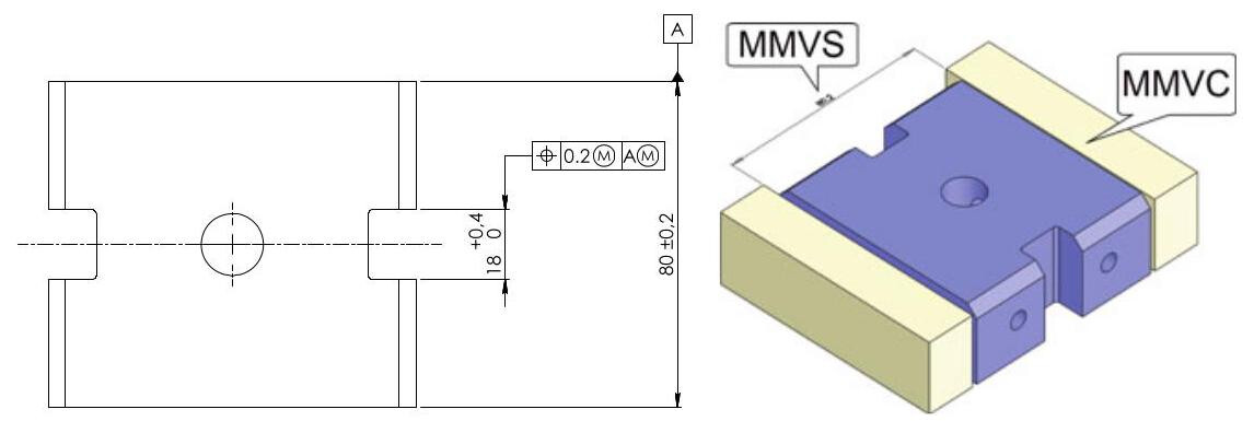
Fig. 6.66 In the case of an external datum (features of size) indicated at MMVC, the datum becomes the median plane of two symmetrical blocks, at a distance from the virtual conditions (in this case, coinciding with the maximum material dimensions of the datum, that is, 80.2 mm)
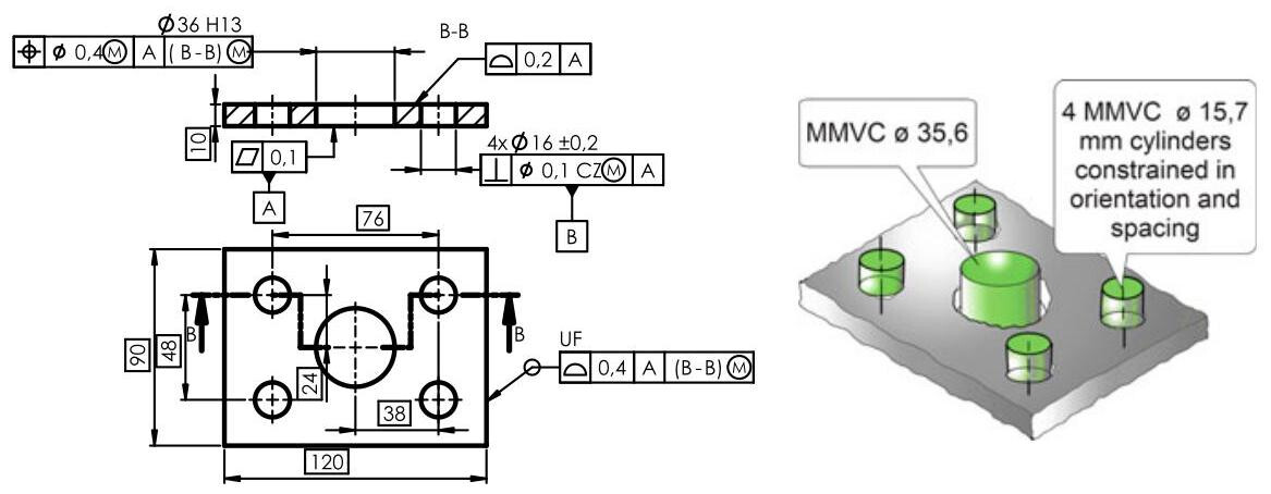
Fig. 6.67 In the case of a common datum constituted by a pattern of holes, it is possible to utilise the maximum and least material modifiers. In this case, the virtual condition is defined by 4 cylinders perpendicular to datum A, constrained in orientation and spacing and of constant dimensions \left( {{15},8 - 0,1 = {15},7\mathrm{\;{mm}}}\right)
6.7 Locked or Released Degrees of Freedom from a Datum
When a datum system is used in a geometrical specification, the situation feature of the tolerance zone is oriented or located on the basis of the datum system defined in the datum section of the tolerance indicator. However, it is possible to vary the number of degrees of freedom eliminated from the datums, according to the design requirements, by utilising PL, SL, PT, >< modifiers after the indication of the datum and enclosing them in square brackets (Fig. 6.68). The complementary indications [PL], [SL] and [PT] are only used when the situation feature of a plane, a straight line or a point is needed, respectively.
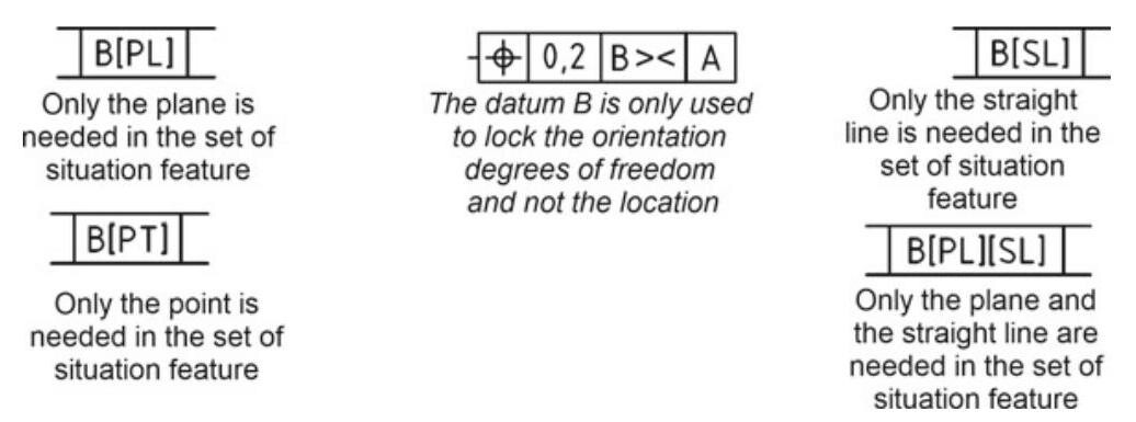
Fig. 6.68 By default, a datum restricts all the possible degrees of freedom but, through some modifiers, it is possible to indicate the degrees of freedom that are blocked by a datum feature
The complementary indication > < is only used to lock the orientation degrees of freedom, and not the location, and should be omitted when the geometrical characteristic only controls the orientation of the feature (e.g. a perpendicular specification).
In Fig. 6.69, for example, the task of locating the tolerance zone has passed from datum B to datum A. Datum B only controls the orientation (that is, it only restricts two degrees of freedom instead of three).
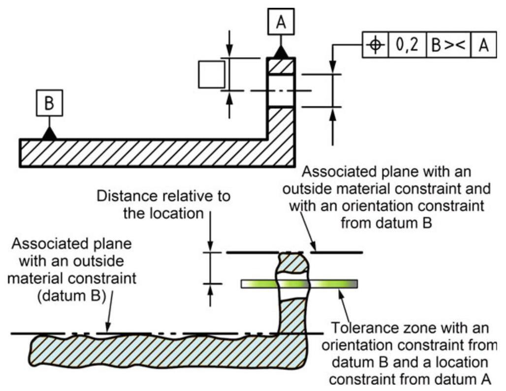
Fig. 6.69 Example of a datum with the >< modifier. Datum B should orientate and locate the tolerance zone (constrained by three degrees of freedom). The use of the “><” modifier only allows the orientation to be controlled, while the location of the tolerance zone is left to datum A
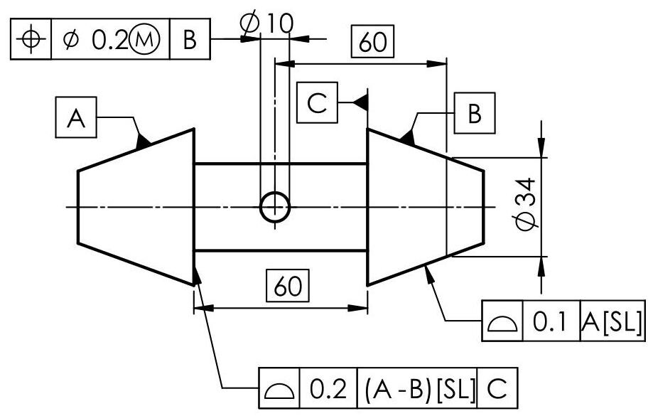
Fig. 6.70 The situation feature used to establish datum A is the axis of the cone. The situation features used to establish datum B are the axis of the cone and one point on the axis. When a complementary indication (SL, PL or PT) applies to all the elements of the collection of surfaces of a common datum, the sequence of letters that identify the common datum should be indicated within parentheses
Only datum A in Fig. 6.70 is used to orient and locate the tolerance zone relative to one of the situation features of the associated cone (only the axis of the associated cone). Datum B is used to orient and locate the tolerance zone of the 10mm hole to the situation features of the associated cone, that is, the axis of the cone and a particular point along this axis, defined by the location. When a complementary indication (SL, PL or PT) applies to all the elements of the collection of surfaces of a common datum, the sequence of letters that identify the common datum should be indicated within parentheses.
6.7.1 Customised Datum Reference Frame in the ASME Standards
Datums in the ASME standard have the task of defining the DRF (Datum Reference Frame), that is, the 3 perpendicular plane datum system that defines the origin for the measurements and allows a workpiece to be blocked during an inspection or during working operations. A primary datum eliminates three degrees of freedom (2 rotational, that is, u and v, and one linear, z). A secondary datum eliminates two degrees of freedom, (linear y and rotational w). Finally, a tertiary datum eliminates the last degree of freedom, that is, of translation x. In short, a datum system is defined to restrict some degrees of freedom related to its use.
The ASME Y14.5 standard introduced the possibility of customising the number of degrees of freedom eliminated from each plane of the DRF. For example, it is possible to indicate, in brackets, the number and type of degrees of freedom that have been eliminated, with reference to the datum system. Primary datum A in Fig. 6.71 eliminates three degrees of freedom, that is, u, v and z; secondary datum B (axis of a 14mm hole) eliminates two degrees of translational freedom,that is,x and y, and tertiary datum C has the task of restricting rotation w in order to control the location error of the 38mm hole and of the four 14mm diameter holes.
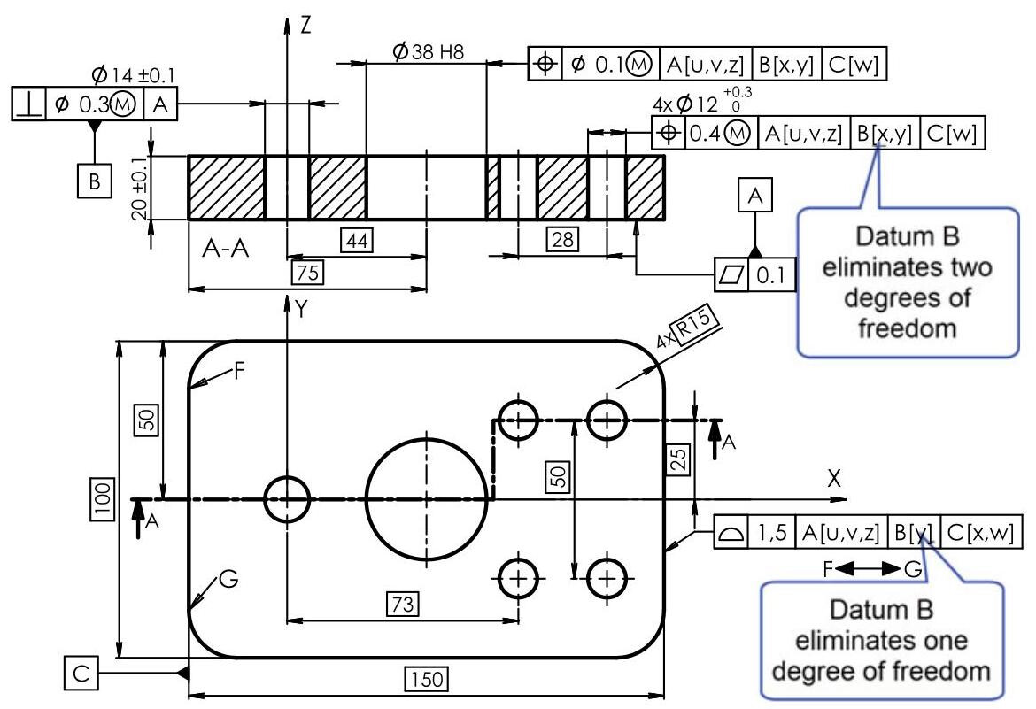
Fig. 6.71 In the ASME standards, the eliminated degrees of freedom are indicated in square brackets. It is possible to vary the number of degrees of freedom eliminated by each datum by, for example,transferring the task of limiting the degrees of freedom along direction x from datum B to datum C
Instead, the task of limiting the degree of freedom along direction x has passed from datum B to datum C to locate and orientate the profile tolerance zone, and datum B therefore only eliminates one degree of freedom.
When multiple datum reference frames exist, and it is desirable to label the axes of the coordinate system (X, Y, and Z), any labelled axes should include a reference to the associated datum reference frame. In Fig. 6.72, the X, Y and Z axes for the three datum reference frames are identified as [A, B, C], [A, B, D] and [A, B, E], and they represent the datum features of each DRF.
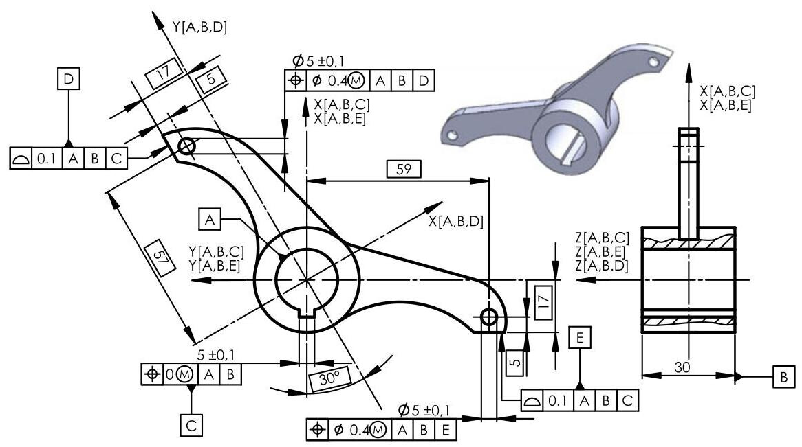
Fig. 6.72 When multiple datum reference frames exist, the labelled axes should include a reference to the associated datum reference frame. The X, Y and Z axes of the three datum reference frames are identified as [A, B, C], [A, B, D] and [A, B, E], and they represent the datum features of each DRF
6.8 Datum Targets
When it is preferred not to use a complete integral feature to establish a datum feature, it is possible to indicate portions of the single feature (areas, lines or points) and their dimensions and locations. These portions are called datum targets. They usually simulate the interface between the considered single feature of the workpiece and one or more contacting ideal features (assembly interface features or fixture features).
Datum targets are used in the case of complicated and irregular forms, such as those produced for moulding or casting, or for non-planar and distorted surfaces. Datum targets are a compromise between the functioning of a feature and repeatability of the measurement and, even when indicated on the drawing of a workpiece, they in fact describe the form and location of the control features that are utilised to simulate a datum plane.
Datum targets should be used in the following cases:
(a) when only a portion of a part feature is functional and can be used as a datum feature;
(b) when an irregular or regular form prevents the use of a planar surfaces as a datum;
(c) when the workpiece becomes unstable during the verification process, once it has been located with its datum surface.
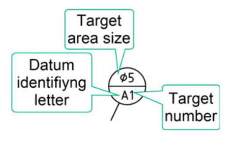
Fig. 6.73 Datum target indicator constituted by a datum target frame, a datum target symbol and a leader line
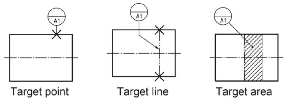
Fig. 6.74 Datum targets are made up of points, lines and planar areas (of any form) or cylindrical contact planes, bordered by a 5.1 line, according to ISO 128-4
A datum target is indicated by a datum target indicator, which is constituted by a datum target frame, a datum target symbol and a leader line. Datum targets are indicated by a circle divided into two compartments by a horizontal line (Fig. 6.73). The lower compartment is reserved for a letter, which represents the datum feature, and for a number, which indicates the number of the datum target. The upper compartment is reserved for complementary information, such as the dimensions of the datum target zone. If there is not enough space in the compartment, the information may be placed outside the circle and joined with a leader line.
Datum targets are established (see Fig. 6.74) with points, lines and planar contact areas (of any form) or cylindrical areas, bordered by a 5.1 line according to ISO 128- 4. Each datum target should be located by means of theoretically exact dimensions, in that they do not refer to the features of a workpiece, but instead define the size and characteristics of the control system. Moreover, the theoretically exact dimensions not only ensure repeatability of the measurements, but can also refer to the degree of precision of the inspection system.
If the datum target on a workpiece is a point, it is indicated with a cross; in the case shown in Fig. 6.75, the primary datum is defined by at least three points of contact (A1, A2 and A3), the secondary datum by two points (B1 and B2) and the third by point C1; the control equipment, whose pins simulate the datum targets in the drawing, is also visible in the same figure.
If the datum target is made up of a line, it is indicated with two crosses united by a fine 5.1 double-dashed line which, when this line is not closed (open line), is terminated by two crosses
,as shown in Fig. 6.76; finally,if the datum target is made up of a flat contact zone, it is indicated with a hatched area whose borders are defined by a fine 5.1 double-dashed line (Fig. 6.77) or even by a cross, when there is no risk of misunderstanding in the identification of the datum.
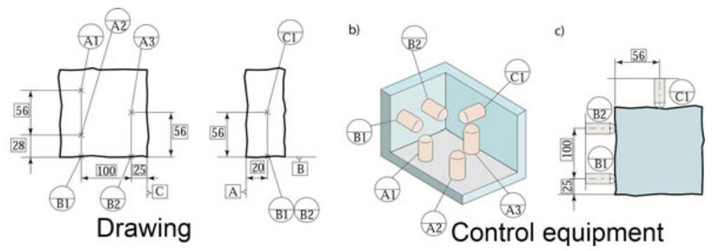
Fig. 6.75 Datum targets made up of points and the relative control equipment with spherical-tipped gauge pin verification
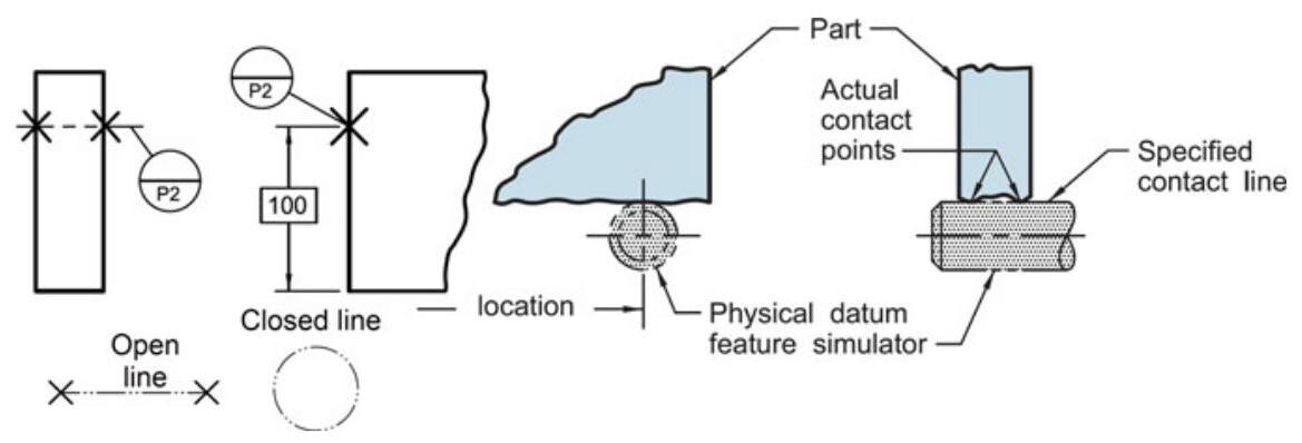
Fig. 6.76 Datum targets made up of lines simulated in control equipment by the side of a gauge pin
If the datum is on the opposite side to that indicated by the symbol, the leader line is dashed, as shown in Fig. 6.78.
In order to express the use of datum targets, the datum feature identifier should be repeated close to the datum feature indicator, and should be followed by a list of numbers (each number separated by a comma followed by a space) to identify the datum target identifier (Fig. 6.79).
It is also possible to specify datum targets on cylindrical surfaces, as shown in Fig. 6.80 [1]: the A1 datum target is specified with a circular datum target line (which is visible as a line in the image), while datum B is specified with a cylindrical datum area; the verification requires the use of variable diameter gauges.
Figure 6.81 shows a typical application of a datum target: the assembly requirement of the plated component requires the indication of an “area” datum target.
The drawing of a workpiece, obtained by means of casting, is shown in Fig. 6.82, with indications of three datum targets, which define a datum system with three perpendicular planes, in which:
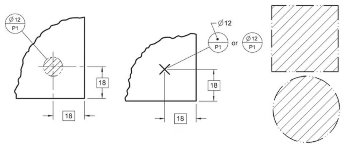
Fig. 6.77 If the datum target is made up of a planar contact zone, it is indicated by a hatched area in which the borders are defined by a fine 5.1 double-dashed line
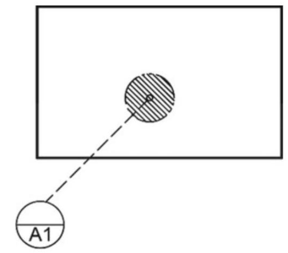
Fig. 6.78 If the datum target is on the opposite side to that indicated by the symbol, the leader line is dashed
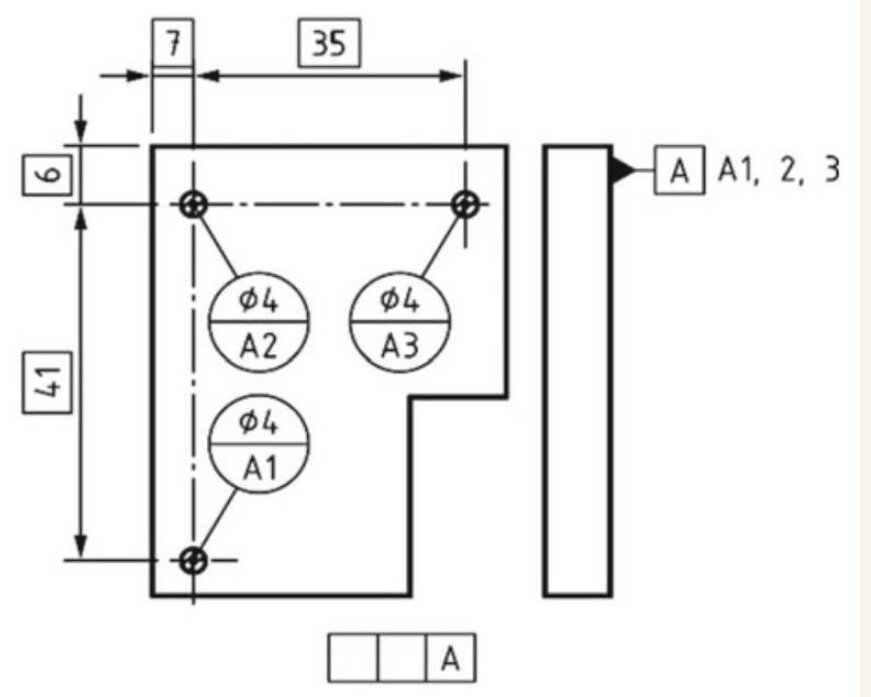
Fig. 6.79 To express the use of datum targets, the datum feature identifier should be repeated close to the datum feature indicator, and should be followed by a list of numbers (each number separated by a comma followed by a space) to identify the datum target identifier
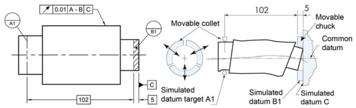
Fig. 6.80 Cylindrical datum target area and line with the simulated gauge
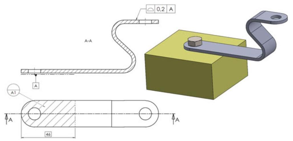
Fig. 6.81 Assembly of the components requires the use of a datum target area. A dashed line is used to indicate the involved surface
- the three datum targets A1, A2 and A3 specify primary datum A;
- the two datum targets B1 and B2 specify secondary datum B;
- the datum target C1 (point) specifies tertiary datum C.
The control equipment is visible in Fig. 6.83; datum plane A is simulated by means of 3 pins with a diameter of 40mm ,datum plane B is simulated by the straight lines between the two pins and datum C is defined by the conical tip of the equipment. Each datum target is located by means of a theoretically exact dimension to indicate that it is necessary to apply the same degree of precision as the control system. Therefore, all the dimensions that locate the datum targets refer to the datum target simulators of the control gauge, and not to the datum features of the workpiece.
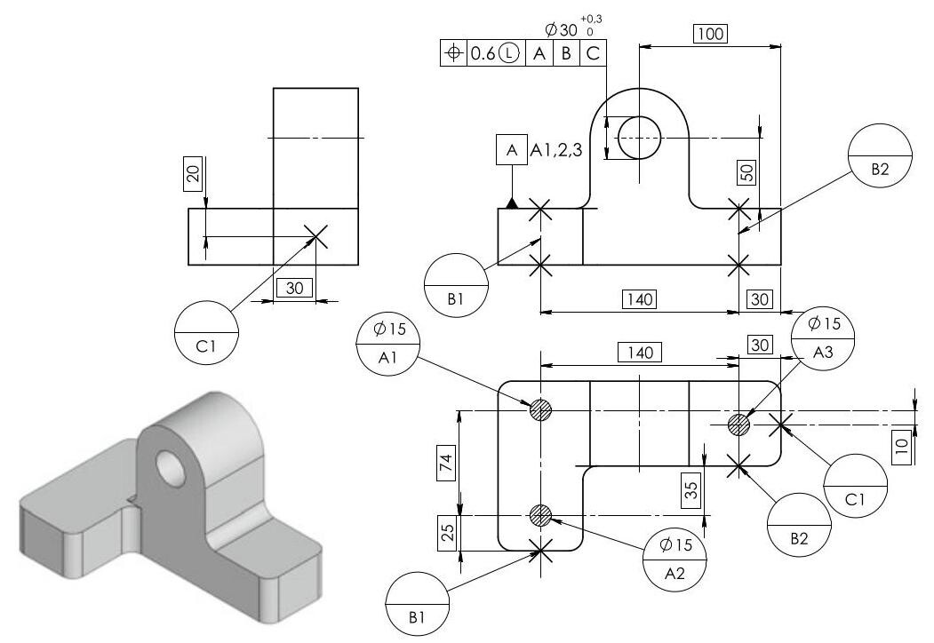
Fig. 6.82 Application of datum targets to establish a datum system. A primary datum plane is established by at least three target points. A secondary datum plane is usually established by two targets. A tertiary datum plane is usually established by one target. A combination of target points, lines and areas may be used and datum targets are located by means of theoretically exact dimensions
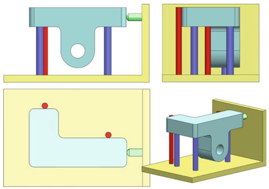
Fig. 6.83 Control equipment for a workpiece that is in contact with the true geometric counterparts for datum features. The datum targets defined by points are simulated by pins with spherical heads. The datum targets defined by lines are simulated by the straight lines of a cylindrical pin. Finally, the datum targets of areas are defined by a pin with a flat head
6.8.1 Contacting Feature
As has already been seen, a datum in the ISO 5459 standard is an “ideal feature which is fitted to the datum feature with a specific association criterion”. In other words, reference is made to an “associated feature” to establish a datum, for example, by associating an ideal tangent plane to a true surface. An interesting novelty introduced by the standard is the definition of “contacting feature”, which defines an ideal feature that is different from a datum feature indicated on the drawing and is associated to such a drawing by means of a “contact” operation (Fig. 6.84).
Let us consider, for example, the drawing of the component shown in Fig. 6.85, produced for moulding, in which datum feature A is the support plane, the second datum is made up of two datum targets, that is, B1 and B2, while the symbols of the two moveable target datums, C1 and C2, are used for the third datum.
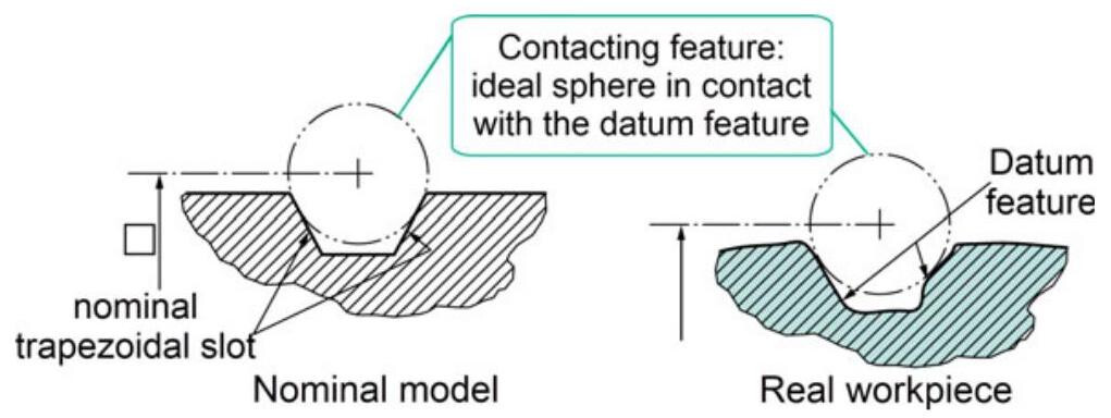
Fig. 6.84 A contacting feature is an ideal feature, with a theoretically exact geometry, which is different from the nominal geometry of the integral geometrical feature with which it is in contact
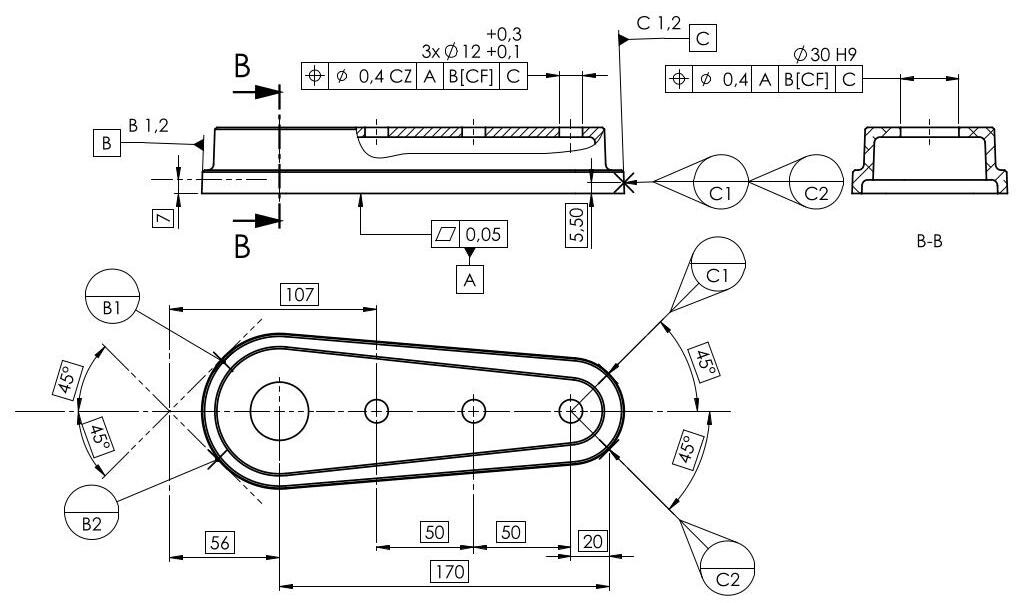
Fig. 6.85 The CF symbol, placed next to the datum feature B indications, defines an ideal feature (V block), which is different from the feature indicated on the drawing and associated to it with a “contact” operation. The two moveable datum target modifiers C1 and C2 are used to define the direction in which the location of the datum target is not fixed
Datum targets B1 and B2 are defined by the interface between the cylindrical surface of the workpiece and a contacting feature. The distance between datum targets B1 and B2 is variable and depends on the actual diameter of the cylinder and the contacting feature, which is defined, in this case, by a “V” block of angle 90° (the associated feature used to establish the datum). The CF symbol,placed next to the datum feature B indications, defines this ideal feature (V block), which is different from the feature indicated on the drawing and associated to it with a “contact” operation.
The modifier [CF] implies that some portions of the workpiece are used to establish the datum, and that the location of the contact between the contacting feature and the workpiece cannot be determined exactly (as it depends on the dimensions and the geometry of the real workpiece).
The two moveable datum target modifiers C1 and C2 are used to define the direction in which the location of the datum target is not fixed. The direction of the motion is indicated by the direction given by the moveable modifier and not by the leader line.
The intention of the design is to allow a simulated datum target (Moveable Datum Target Simulator) to translate or move along a specified direction. By default, a Moveable Datum Target Simulator can translate perpendicularly to the contact surface, but another translation direction may be specified in the drawing and indicated with the theoretically exact dimensions. In our case,the movement direction is at 45° with respect to the median plane of the workpiece.
The workpiece is controlled by means of the functional gauge shown in Fig. 6.86, in which the B1 and B2 fixed datum targets are made up of the sides of the V block, while the C1 and C2 datum targets are simulated by two moveable pins. Figure 6.87 illustrates the control procedure, with the two retractable C1 and C2 pins, which fix the workpiece in the gauge. C1 and C2 move synchronously .
Another example is shown in Fig. 6.88, where a perfect distinction is made between the indications of the datum feature (truncated conic surface) and the contacting features A1 and B1,simulated by two 24mm diameter spheres. Explicit reference to the datum targets, through indications A1 and B1 next to the labels A and B, can also be noted. The corresponding control procedure is carried out through two 24mm spheres of which one corresponds to moveable datum A1. The contacting feature (the sphere) is a different feature from the datum feature indicated on the drawing, which corresponds to the internal conical surface of the component under examination (Fig. 6.89).
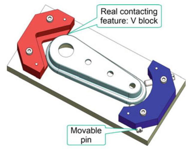
Fig. 6.86 Functional gauge for the control of a workpiece: the fixed datum targets B1 and B2 are constituted by the sides of the V block, while the C1 and C2 datum targets are simulated by two moveable pins. C1 and C2 move synchronously
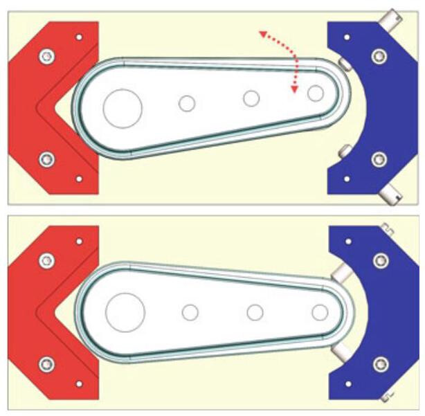
Fig. 6.87 Control procedure, with two retractable pins which fix the workpiece to the gauge. The part is staged on the gauge and datum target simulators C1 and C2 are engaged
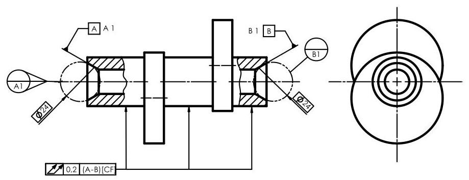
Fig. 6.88 A perfect distinction between the indication of the datum feature (truncated conic surface) and contacting features A1 and A2, simulated by two 24 mm spheres, is obtained by means of the indications of contact feature CF. Explicit reference to the datum target, through the A1 and B1 indications next to the A and B labels, should also be noted
Figure 6.90 shows the association process that should be adopted to obtain datum axis A: the datum is derived from an associated cylinder (e.g. the smallest theoretically circumscribed cylinder) in order to locate the tolerance zone of the profile. The same component is verified with a different setup in the case in which the CF contacting feature symbol is used (Fig. 6.91). In this case, two tangent cylinders, with dimensions, orientation and location fixed on the drawing, are used.
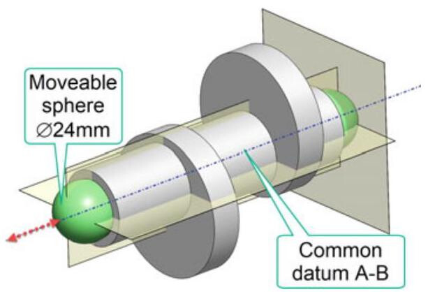
Fig. 6.89 A control procedure carried out by means of two 24mm spheres,one of which corresponds to movable datum target A1
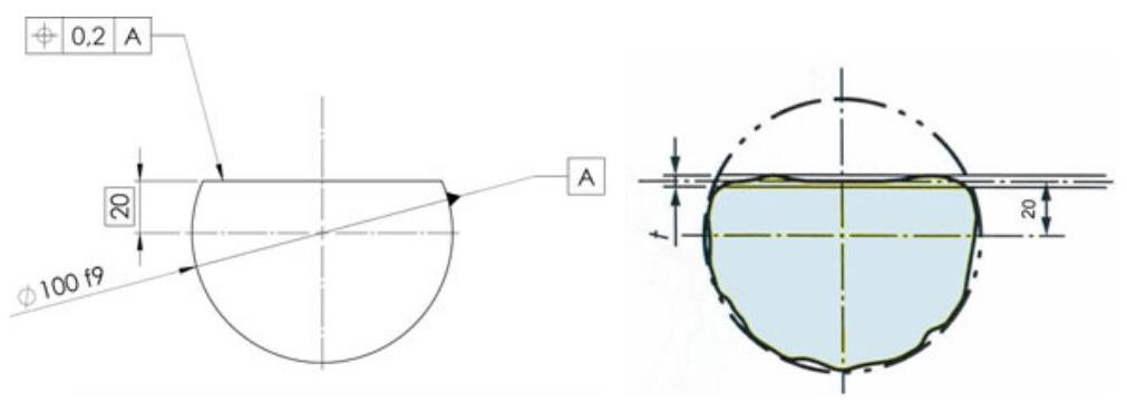
Fig. 6.90 Association of a single datum without a modifier [CF]: datum A is derived from an associated cylinder (e.g. the smallest theoretically circumscribed cylinder) in order to locate the tolerance zone of the profile
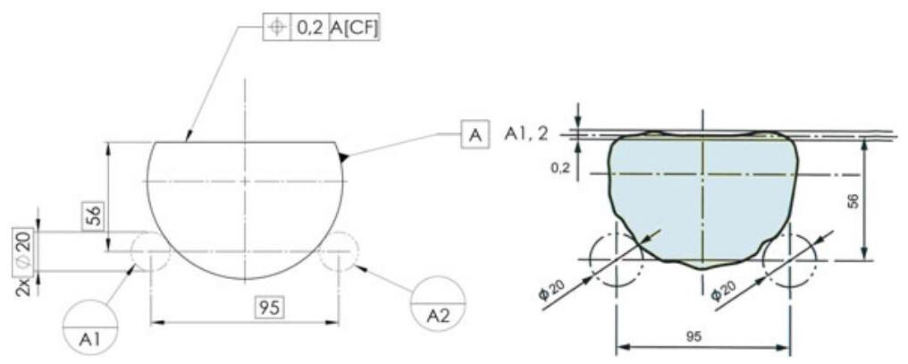
Fig. 6.91 Association of a single datum with a modifier [CF]: the same component as that shown in the previous figure is verified with a different setup. In this case, two tangent cylinders, with the dimensions, orientation and location fixed on the drawing, are used
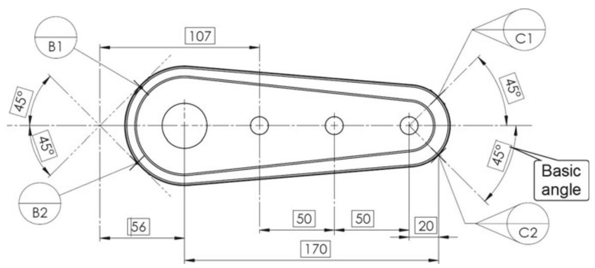
Fig. 6.92 The “movable datum target” symbol in ASME standards is the same as in the ISO standards, but the movement may be indicated through the addition of a line that indicates the direction
6.8.2 Datum Targets in the ASME Standards
The symbols of the datum targets in the ASME Y14.5 standard are basically identical to those of the ISO standard, albeit with some slight differences:
- The datum target line is the same as in the ISO standard (a long-dashed double-dotted line, type 5.1 as in ISO 128-24), but the line does not terminate with two crosses.
- The “movable datum target” symbol is the same as in the ISO standard, but the movement may be indicated for orthographic views through the addition of a line that indicates the direction of movement (see Fig. 6.92). The line element should be specified with one or several basic angles .
- Alternatively, the direction of movement, for drawings that include X, Y, and Z axes to represent the datum reference frame(s), may be indicated using a unit vector designation consisting of i, j, k components (corresponding to the X, Y, and Z axes of the coordinate system), placed in brackets and adjacent to the “movable datum target” symbol. The vector direction is towards the surface of each datum feature. See Fig. 6.93.
- When using datum features defined by datum targets in a feature control frame established by fewer than three mutually perpendicular planes, the datums that are the basis of the datum reference frame should be referenced (Fig. 6.94). The targets that provide a definition of the datums referenced in the feature control frame should be specified in a note, such as: where only datum feature A is referenced, datum features B and C are invoked only to relate the targets that establish datum A.
Some useful advice on datum targets is given hereafter:
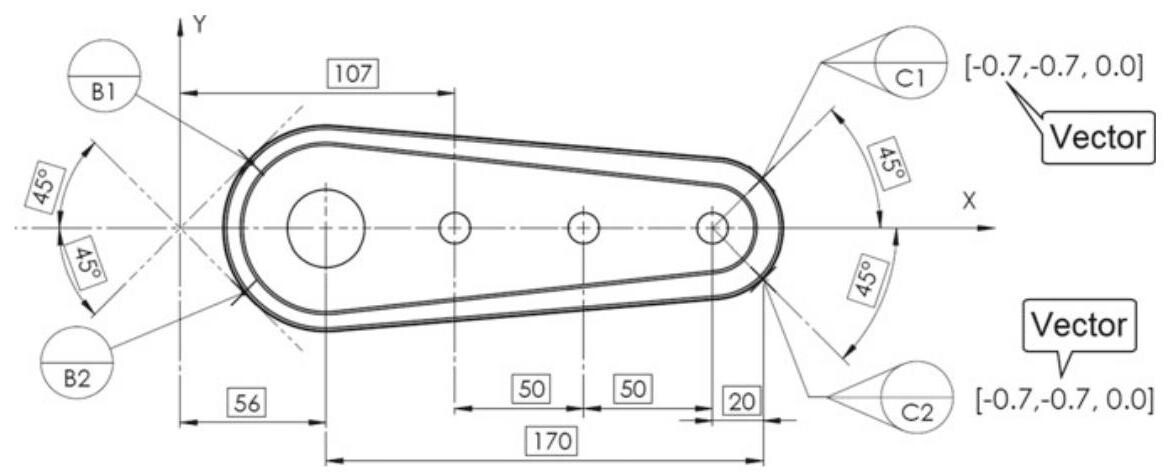
Fig. 6.93 The movement direction may be indicated using a unit vector designation, consisting of i, j, k components, placed in brackets
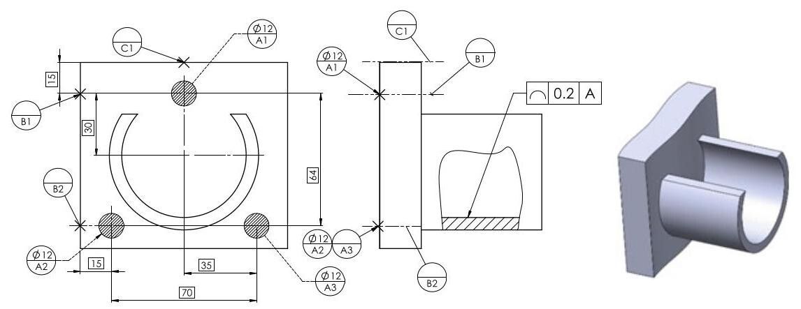
Fig. 6.94 If primary plane A is defined as a datum target, a secondary and a tertiary plane are only invoked to relate the targets that establish datum A
(1) the area indicated by a datum target in a drawing should NOT be realised or carved into the component;
(2) if the primary plane is defined as a datum target, both a secondary and a tertiary plane are mandatory;
(3) if the datum target is an area, contact with the setup feature does not necessarily have to take place over the whole area, as a series of any points within the area specified on the drawing is sufficient.