Abstract In ISO GPS terminology, the maximum material requirement, (MMR) and least material requirement (LMR) represent two of the fundamental rules on which geometrical dimensioning with tolerances is based, and which are the subject of the ISO 2692 standard. The designer, when establishing a maximum or least material requirement, defines a geometrical feature of the same type and of perfect form, which limits the real feature on the outside of or inside the material. MMR is used to control the assemblability of a workpiece while LMR is used to control a minimum distance or a minimum wall thickness. This chapter also introduces the Reciprocity requirement (RPR) and the “zero tolerance” concepts and offers practical examples to guide a designer in his/her choice of the correct requirement from the geometrical tolerance specifications.
5.1 MMR and LMR Requirements
As already seen, the ISO 8015 standard has established the independency principle between dimensional tolerances and geometrical tolerances; however, there are some exceptions contained in the ISO 2692 standard (current version ISO/DIS 2692:2019) which, by using the maximum material requirement (MMR) and least material requirement (LMR), introduce an interdependency between dimensions geometry. The MMR and LMR requirement allow two independent requirements to be combined into one collective requirement, or a maximum material or least material virtual condition to be defined directly, in order to simulate the intended function of the workpiece.
The geometrical tolerance is in fact considered to have been applied, regardless of the size of the workpiece (in ASME Regardless of Feature Size, RFS), each time an exception is not specified (utilising a symbol named modifier), which could be the requirement an envelope (C), or the application the MMR (C) and/or LMR (C) requirements.
In the ISO standard, a distinction is made between:
-
Maximum Material Condition, MMC, the state of the considered extracted feature, where the feature of size is at that limit of size where the material of the feature is at its maximum everywhere, e.g. minimum hole diameter and maximum shaft diameter.
-
Maximum Material Size, MMS: the dimension that defines the maximum material condition of a linear feature of size.
-
Least Material Condition, LMC, the state of the considered extracted feature, where the feature of size is at that limit of size where the material of the feature is at its minimum everywhere, e.g. maximum hole diameter and minimum shaft diameter
-
Least Material Size, LMS, the dimension that defines the least material condition of a feature of size.
5.1.1 Maximum Material Requirement (MMR)
Sometimes called the Maximum Material Principle but, in the ISO GPS terminology, correctly defined as condition or requirement, the Maximum material requirement, (MMR) represents one of the fundamental rules on which geometrical dimensioning with tolerances is based, and which is the subject of the ISO 2692 standard.
The mating characteristics of the workpieces that must be assembled depend on the joint effect of the actual dimensions, and of the form and location errors of the features that have to be mated.
In the case of a mating with clearance, the minimum assembly clearance is obtained when each of the mating features of size is at its maximum material size (e.g. the largest bolt size and the smallest hole size) and when the geometrical deviations (e.g. the form, orientation and location deviations) of the features of size and their derived features (median line or median surface) are also fully consuming their tolerances.
The assembly clearance increases to a maximum when the sizes of the assembled features of size are furthest from their maximum material sizes (e.g. the smallest shaft size and the largest hole size) and when the geometrical deviations (e.g. the form, orientation and location deviations) of the features of size and their derived features are zero.
The consequence is that the prescribed tolerances can in practice be enlarged, without compromising the possibility of mating, when the actual dimensions of the features that have to be mated do not reach the values corresponding to the maximum material condition (Fig. 5.1).
This constitutes the MMR principle, or maximum material requirement, and it is indicated on a drawing with the symbol (C). This symbol is inserted after the value of a tolerance in a tolerance frame indicator, and should be read as “the geometrical tolerance here imposed and foreseen for the case in which the linear dimensions are under the maximum material condition”. The foreseen tolerances can therefore be increased by a value that is equal to the difference between the dimension of the maximum material and the actual dimension (Fig. 5.2). An increase in the geometrical tolerance can obviously be applied when the feature to which the MMR requirement has to be applied is a feature of size (to which a dimensional tolerance can be associated), with an axis or a symmetry plane, such as a hole, a groove or a pin. The advantages that can be obtained pertain to an economy in the production, as a result of the enlargement of the limits of the tolerances, and a reduction in the wastes, since it is possible to accept features which, although the geometrical tolerances are not within the prescribed limits, in practice offer the same functional characteristics as the features achieved within the limits. An increase in the location tolerance can in general be accepted, for example, for the distances between the centres of holes for bolts, coach screws, etc., while it is not admissible for the axes of gears, dowel pins, kinematic connections, etc.
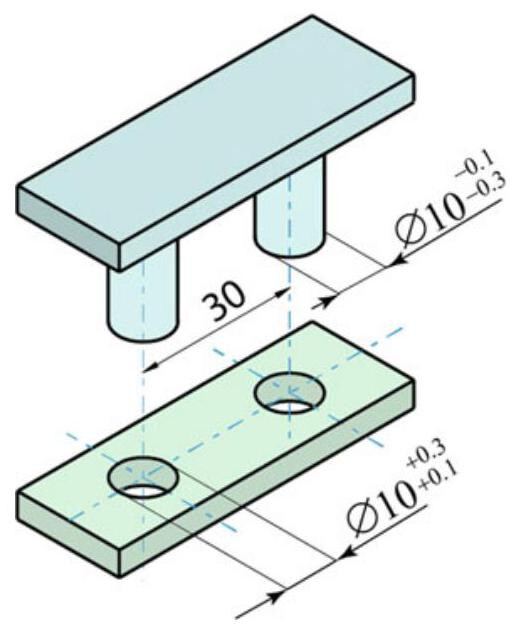
Fig. 5.1 The mating of a plate with two through holes and a feature with two pins; the most critical conditions pertaining to the distance between their centres occur for the maximum material condition, that is, when the hole is at the minimum diameter (Ø10.1) and the pin is at the maximum diameter (69.9). It is obvious that when the hole is at a diameter of 10.3mm and the pin is at a minimum diameter of 9.7mm ,the tolerance on the distance between their centres could be increased without jeopardising the mating
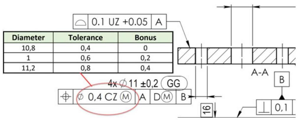
Fig. 5.2 An increase in the location tolerance (Bonus) due to the presence of the @modifier for the component shown in Fig. 3.1. The increase is equal to the difference between the measured dimension and the maximum material dimension
In short, the assembly function is controlled by the maximum material requirement, which is indicated on drawings with the symbol (C).
The designer, when establishing a maximum material requirement, defines a geometrical feature of the same type and of perfect form of a value that is equal to the Maximum Material Virtual Size (MMVS), which limits the real feature on the outside of the material. In this case, the MMR is used to control the assemblability of the workpiece, and the real feature cannot violate the MMVS.
The Maximum Material Virtual Size is the size generated by the collective effect of the maximum material size (MMS) of a feature of size and the geometrical tolerance (form, orientation or location) given for the derived feature of the same feature of size. The Maximum Material Virtual Condition (MMVC) is the state of an associated feature of the maximum material virtual size, MMVS.
A shaft subjected to dimensional tolerances on the diameter is shown in Fig. 5.3, for which a straightness tolerance of 0.1mm is indicated. In this case,the tolerance refers to the straightness of the derived median line, since the symbol is placed on the diameter dimension. If the maximum material requirement is not indicated, the value of the straightness tolerance remains constant, since the value of the diameter varies from a maximum to a minimum, as a result of the independency principle. In this case, the straightness tolerance always imposes that the derived median line should always fall within a cylindrical tolerance zone of 0.1mm.
When an MMR symbol is included, the intended function of the shaft indicated in Fig. 5.3 could be a clearance fit with a hole of the same length as the toleranced cylindrical feature. In this case, the extracted feature should not violate the maximum material virtual condition,MMVC,which has the MMVS diameter 35.1mm ,since MMVS is obtained with the following formula for an external feature of size:
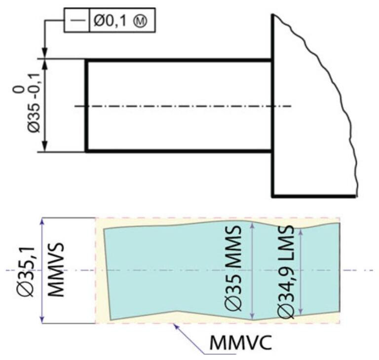
Fig. 5.3 Application of MMR for an external cylindrical feature on the basis of size and form (straightness) requirements
At the same time, the extracted feature should have a larger local diameter than LMS 34.9mm and a smaller one than MMS 35.0mm . The orientation and location of the MMVC are not controlled by any external constraints.
The designer, through the implicit indications of the MMVC, is able to ensure full functionality and interchangeability of the produced workpieces, all at a minimum cost. The 35mm hole in the plate in Fig. 5.4 has an MMVC of 35.1 mm,which is obtained by subtracting the tolerance of 0.1mm from the maximum material size (MMS) of 35.2mm . For internal features of size,MMVS is obtained from the formula:
The intended function of the hole could be for assembly with a pin shaft, where the functional requirement is that the two planar faces should be in contact and, at the same time, the pin should fit into the hole. The extracted feature should not violate the maximum material virtual condition, MMVC, which has the MMVS diameter 35.1mm and the extracted feature should simultaneously have a smaller local diameter than LMS 35.3mm and larger than MMS =35.2mm . MMVC is orientated perpendicular to the datum and the location of the MMVC is not controlled by any external constraints. In short, the boundaries of the hole must not violate the MMVC cylindrical boundary.
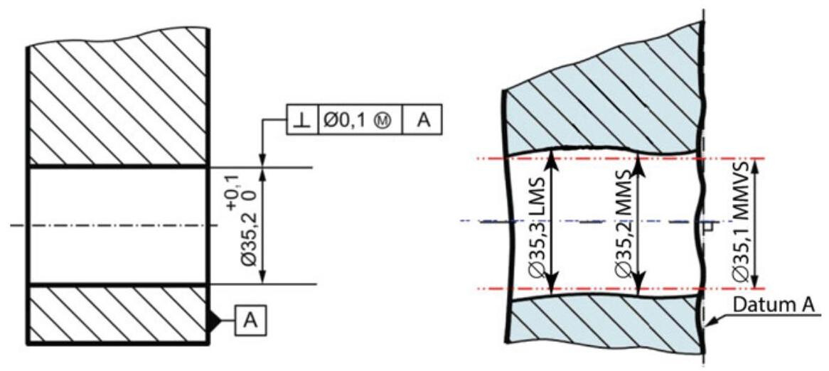
Fig. 5.4 An application of MMR for an internal cylindrical feature on the basis of size and orientation requirements
5.1.2 Least Material Requirement (LMR)
A least material requirement is designed to control, for example, the minimum wall thickness, thereby preventing breakout (due to pressure in a tube), the maximum width of a series of slots,etc. It is indicated on drawings with the symbol Q In the case in which the Least Material Requirement, LMR, is foreseen, it is not difficult to understand why reference is made to holes which have the maximum admissible diameter according to the prescribed dimensional tolerance, or to minimum diameter shafts.
Again, in this case, when different conditions from the LMC are available, an increase in the form and location tolerances can be made that is equal to the difference between the actual dimensions and that of the least material.
In short, the symbol Gis used on the drawing with the objective of guaranteeing the existence of a resistant section, or of guaranteeing a minimum distance. Figure 5.5 shows a typical application of the LMC requirement introduced to protect the minimum distance of the edge of a hole with respect to the edge of the workpiece, but at the same time to permit an increase in the location tolerance.
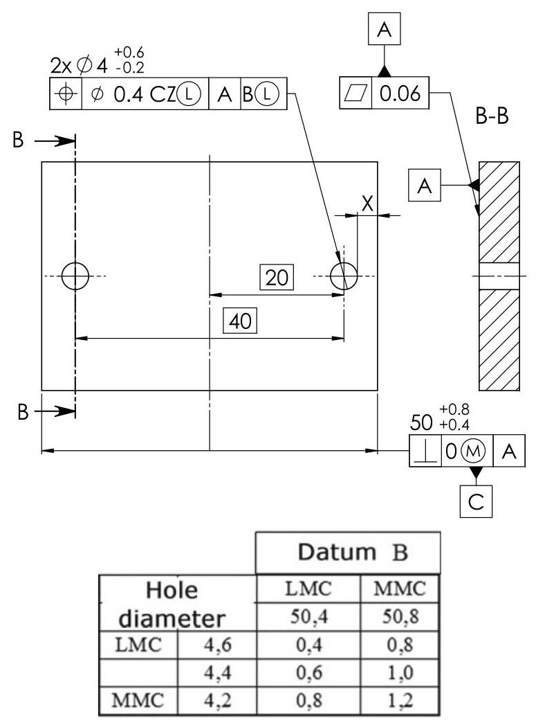
Fig. 5.5 Utilisation of the LMR requirement to control a minimum distance
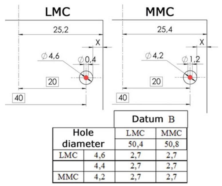
Fig. 5.6 The minimum distance X is protected for any dimensional condition (2.7 mm)
The worst mating condition occurs when the hole has the maximum allowed dimensions (or when the datum has a minimum width, LMC), and it is in fact in this condition that the localisation tolerance of 0.4mm is defined. When a hole is produced with smaller dimensions (or when the datum is produced with greater dimensions), it is possible to increase the localisation tolerance up to a value of 1.2mm ; as can be seen in the dimension chain (Fig. 5.6), the distance X remains the same under any condition, in that at the MMC state:
While, at the LMC state:
The least material requirement can also be characterised by a collective requirement pertaining to the size and the geometrical deviation of the feature of size. When a designer introduces the LMR symbol, he/she defines a geometrical feature of the same type and of perfect form, with a value equal totheLeast Material Virtual Size (LMVS) which limits the real feature on the inside of the material.
The Least Material Virtual Size is the size generated by the collective effect of the Least material size (LMS) of a feature of size and the geometrical tolerance (form, orientation or location) given for the derived feature of the same feature of size. The Least Material Virtual Condition (LMVC) is the state of an associated feature of maximum material virtual size, LMVS.
The 4mm hole in the plate in Fig. 5.5 has an LMVC of 5mm ,which is obtained by adding the tolerance of 0.4mm from the minimum material size (LMS) of 4.6mm . For internal features of size, LMVS is obtained from the formula:
The LMR in Fig. 5.7 requires the extracted surface of the hole to fall inside the LMVC boundary.
Figure 5.8 shows an example of coaxiality control with a datum established from an external feature of size referenced at LMC. The least material virtual size (LMVS) of an external feature of size is obtained from the formula:
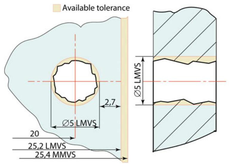
Fig. 5.7 The LMR in Fig. 5.5 requires that the extracted surface of the hole should fall inside the LMVC boundary
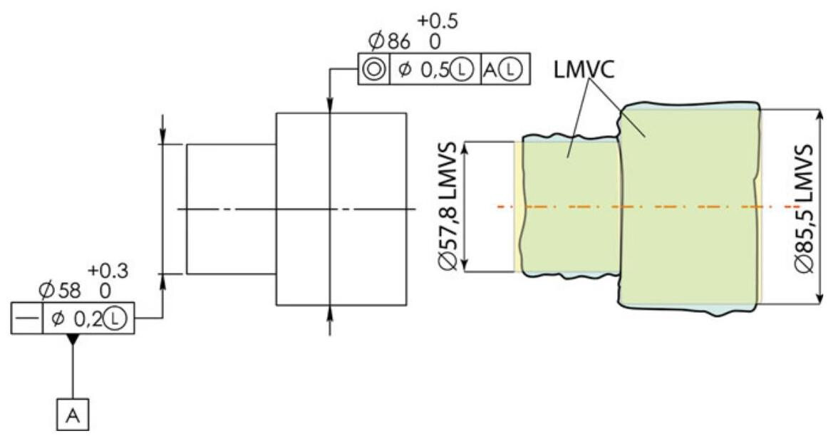
Fig. 5.8 An example of an LMR for an external cylindrical feature based on size and location (coaxiality) requirements with the axis of a cylindrical feature as the datum referenced at LMR
LMVS = LMS - \delta ,where \delta is the geometrical tolerance
LMR requires that the extracted surface of a feature of size should fall outside the LMVC boundary. The location of the LMVC is at 0\mathrm{\;{mm}} from the axis of the LMVC of the datum feature. The extracted feature of the toleranced feature should not violate the least material virtual condition, LMVC, which has the diameter LMVS = {85.6}\mathrm{\;{mm}} . The same extracted feature should have a larger local diameter than LMS = {86}\mathrm{\;{mm}} and smaller than MMS = {86.5}\mathrm{\;{mm}} .
The extracted feature of the datum feature should not violate the least material virtual condition,LMVC,which has an LMVS diameter = {57.8}\mathrm{\;{mm}} . The same extracted feature should have a larger local diameter than LMS = {58}\mathrm{\;{mm}} and smaller than MMS = {58.3}\mathrm{\;{mm}} .
5.1.3 Reciprocity Requirement (RPR)
The reciprocity requirement (RPR) is an additional requirement, that may be used together with the maximum material requirement and the least material requirement, and is indicated on a drawing with the symbol (R). RPR allows a size tolerance to be enlarged whenever the geometrical deviation on the actual workpiece does not take full advantage of, the maximum material virtual condition or the least material virtual condition, respectively.
RPR is basically an additional requirement for a feature of size and it is introduced, in addition to the maximum material requirement, MMR, or the least material requirement, LMR, to indicate that the size tolerance is increased by the difference between the geometrical tolerance and the actual geometrical deviation.
The reciprocity symbol defines equivalent requirements to specifications with dimensional and geometrical requirements with an indication of zero tolerance with a modifier (C). A reciprocity requirement should only be indicated in the tolerance section of the tolerance indicator. As stated in the standard, the modifier shall not be indicated in the datum section of the tolerance indicator.
RPR allows the distribution of the variation allowance between dimensional and geometrical tolerances to be chosen on the basis of the manufacturing capabilities. It should be noted that this requirement is not present in the ASME standard.
Let us consider the workpiece shown in Fig. 5.9,which has four 9\mathrm{\;{mm}} diameter holes and a position tolerance of {0.4}\mathrm{\;{mm}} ; the maximum material virtual size (MMVS) of the hole,as has already been seen,is calculated from the difference {8.8} - {0.4}\mathrm{\;{mm}} \; = {8.4}\mathrm{\;{mm}} ,which represents the internal MMVC boundary that cannot be violated.
Therefore, a hole verified with a diameter of 8,4 mm could be mated without any problems if it has a zero-position error, but the component would nevertheless be discarded during the dimensional control.
In order to avoid this problem, it is possible to utilise the zero tolerance method (Fig. 5.10), that is, the hole is produced in such a way that a position tolerance of zero is obtained for the virtual dimension but, at the same time, the dimensional tolerance zone is increased.
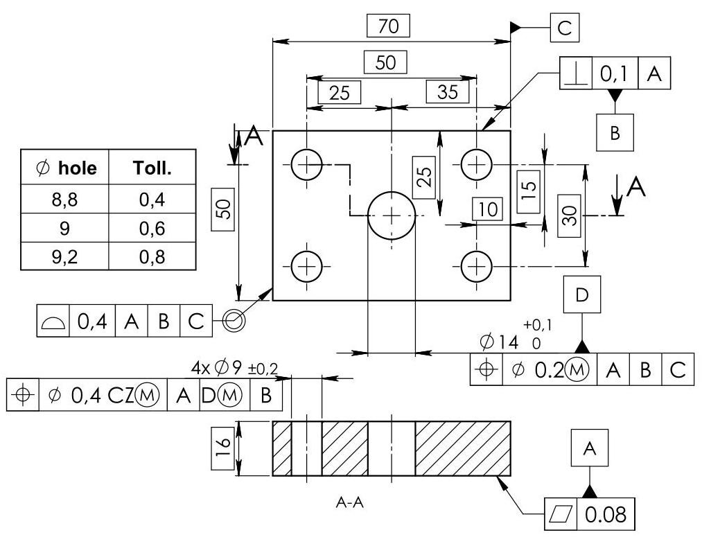
Fig. 5.9 An indication of a position tolerance: the table shows the variations of the tolerance as the diameter of the hole varies as a result of utilising the maximum material requirement, MMR
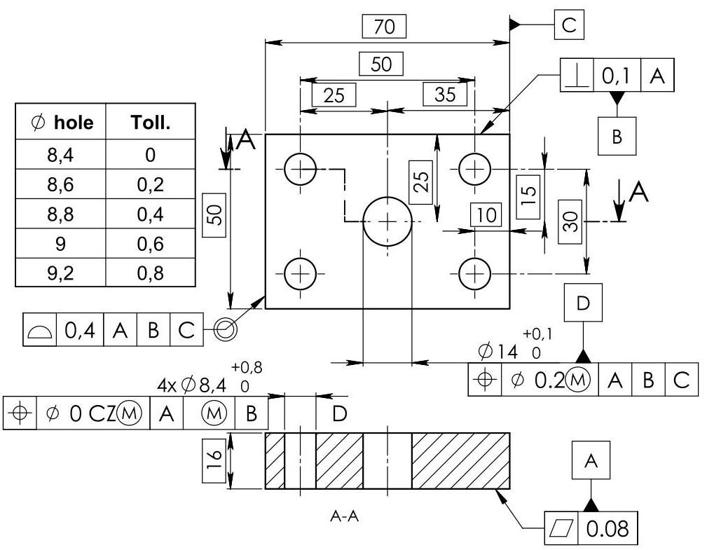
Fig. 5.10 An indication of zero tolerance. As can be seen in the table, the tolerance is only zero if the hole is produced at the maximum material condition (8.4mm) and increases up to 0.8mm
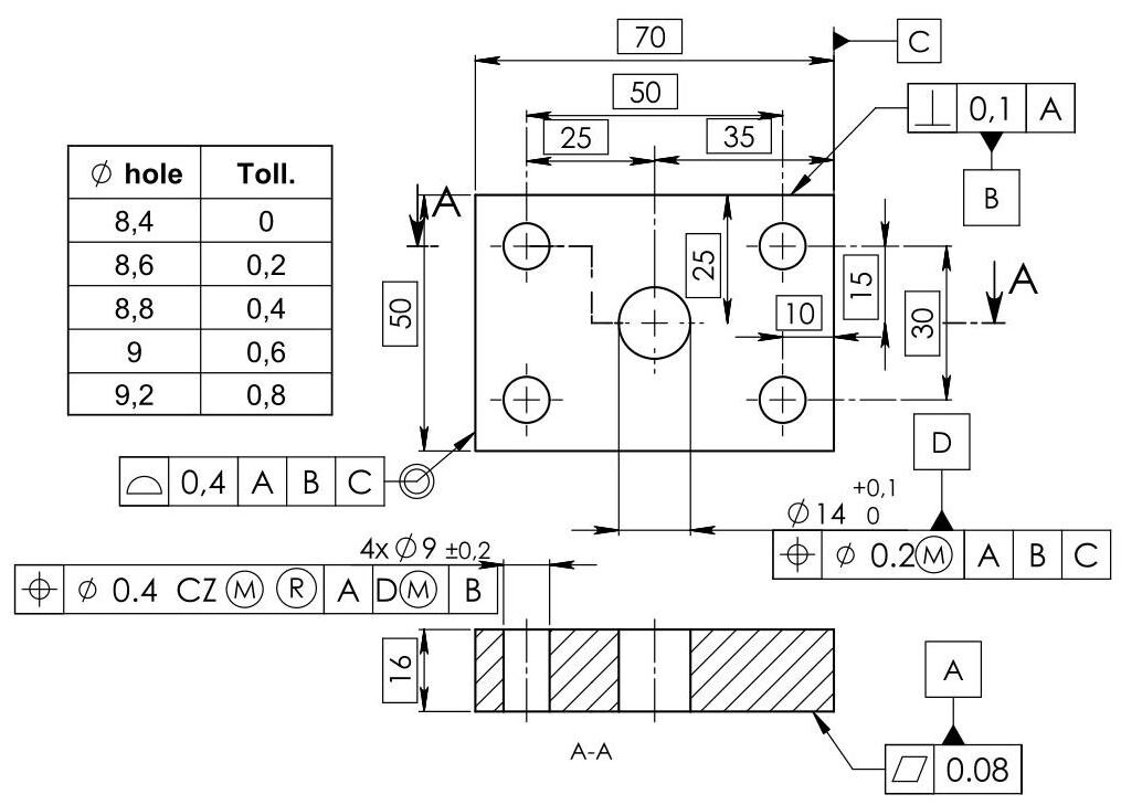
Fig. 5.11 The drawing above has the same dimensions as Fig. 5.9, but the reciprocity symbol makes it possible for the allowed variations between the dimensional and geometrical errors to be distributed. In practice, the same effect as a zero tolerance is obtained
Several advantages can thus be obtained, including:
(a) full use of the dimensional tolerance bonus (from 0 to 0.8mm );
(b) the possibility of controlling the position and the lower dimensional limits of the hole at the same time with a functional gauge;
(c) a reduction in the production costs, since reusable parts are not rejected.
The additional requirement of RPR in Fig. 5.11 changes the size tolerance of the hole as a result of adding the collective MMR requirement, thereby obtaining the same effect as the indication of a zero tolerance, without any change in the drawing.
From the functional point of view, that is, as far as assembly problems are concerned, the three specifications are equivalent; from the production point of view, undoubtable advantages can be obtained.
In this sense, the allowable positional tolerance values are listed on the vertical scale in the analysis chart in Fig. 5.12. The horizontal scale shows the virtual condition and hole sizes of the part. In the case in which the zero tolerance is not used, the cyan coloured area represents the zone of the workpieces accepted during the control according to the drawing specifications, while the parts that fall into the yellow area are rejected during the control, even though they are acceptable from the functional point of view.
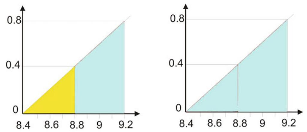
Fig. 5.12 Tolerance analysis charts for the component dealt with in Fig. 5.9; the workpieces in the chart on the left that fall into the yellow zone are rejected during the control, even though they are acceptable from a functional point of view; in the case of the use of a zero tolerance or RPR (chart on the right), the cyan area in the chart becomes larger, thus allowing a reduction in waste and more manufacturing flexibility to be achieved
When the zero-tolerance concept, or the reciprocity requirement, is adopted, the cyan area in the chart becomes larger, thus allowing a reduction of the rejected parts and greater manufacturing flexibility.
5.2 Direct Indication of Virtual Size
The new ISO 2962 standard allows a designer to directly specify the value of the maximum virtual size or the least material virtual size. In this case, the calculated value of the virtual size should be indicated between brackets in the tolerance indicator. If a size is also specified for the considered feature, it should be considered as an independent specification according to ISO 14405-1. No collective requirement is created between the two specifications (size specification and geometrical specification) in the case of the direct indication of the maximum material or least material virtual size.
When the maximum material requirement, MMR, applies to the tolerance feature, and the direct indication of virtual size is selected, then the value of the maximum material virtual size (MMVS) should be indicated after the @symbol between brackets (Fig. 5.13). The \varnothing symbol should be omitted when the feature of size is not a diameter. When a direct indication of the maximum material virtual size (MMVS) is selected, no geometrical tolerance value should be indicated before the symbol. The same rule applies to the LMR requirement (Fig. 5.14).
When the maximum material requirement applies to a datum and the direct indication of virtual size is selected, then the maximum material virtual size (MMVS) for the datum should be indicated with a numerical value between brackets in the datum indicator, after the datum feature symbol, as shown in Fig. 5.15. The \varnothing symbol should be omitted when the feature size is not a diameter. It is necessary to point out that, for the interpretation of straightness, the extracted feature should not violate the maximum material virtual condition, MMVC, which has an MMVS diameter = \; {29.9} - {0.2} = {29.7}\mathrm{\;{mm}} . The extracted feature should have a smaller local diameter than LMS = {29.9}\mathrm{\;{mm}} and larger than MMS = {30.3}\mathrm{\;{mm}} . The extracted feature of the datum feature should not violate the maximum material virtual condition, MMVC, which has an MMVS diameter = {29.5}\mathrm{\;{mm}} . At the same time,the extracted feature of the toleranced feature should not violate the maximum material virtual condition, MMVC, which has an MMVS diameter = {49.9}\mathrm{\;{mm}} . The same feature should have a smaller local diameter than LMS = {50.4}\mathrm{\;{mm}} and larger than MMS = {50}\mathrm{\;{mm}} . The MMVC is located at 0\mathrm{\;{mm}} from the axis of the MMVC of the datum feature.
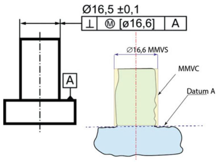
Fig. 5.13 Direct indication of an MMVS on an external feature
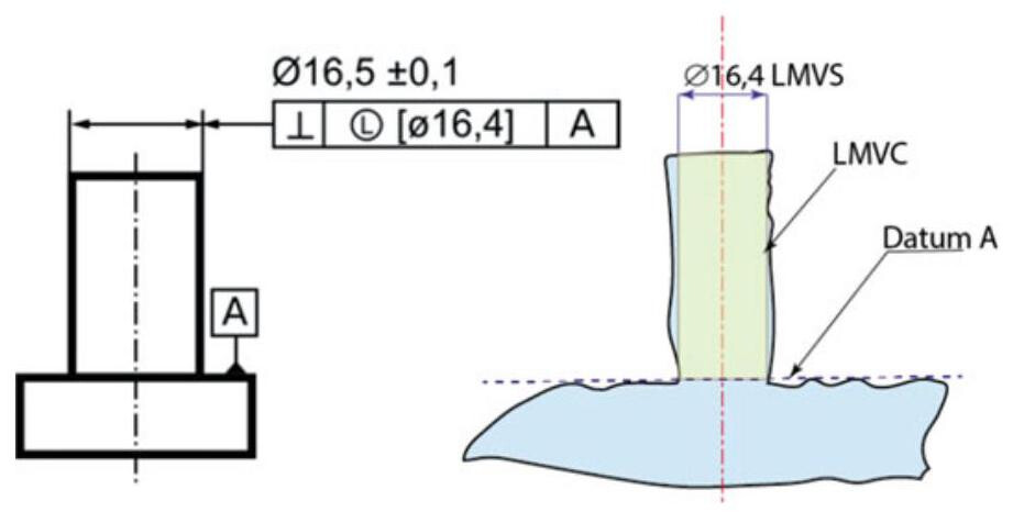
Fig. 5.14 Direct indication of an LMVS on an external feature
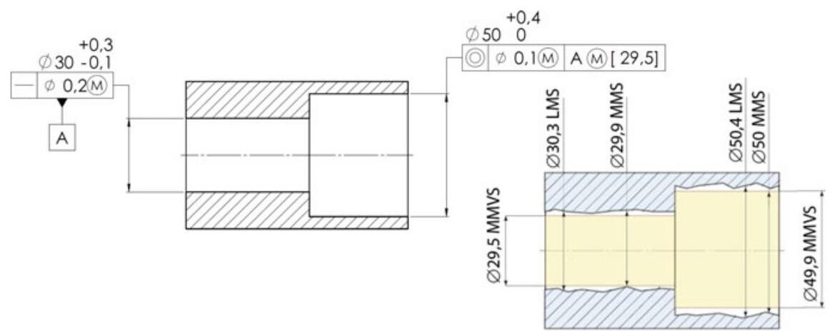
Fig. 5.15 Example of a direct indication of an MMVS on a datum
5.3 When to Use MMR, LMR, and RFS
The decision to choose an RFS, MMR, LMR or RPR requirement depends on the function of the workpiece. MMR is generally chosen when the parts have to be assembled with a mating with clearance (i.e. fixed fastener), but it is useful to allow additional maximum tolerances to reduce the manufacturing costs.
LMR is useful when a designer has the goal of guaranteeing a minimum distance or a critical wall thickness. RPR is used to enlarge the size tolerance, for example, in a non-functional assembly. Finally, RFS (without any modifier) is used when any additional tolerance, such as the control of a position tolerance of a locating pin, can compromise the functionality of the workpiece.
It should be noted that, in many cases, an additional tolerance does not have any impact on the function, and therefore does not make the part work better. The additional variation allowed by MMR may lead to a reduction in the cost of manufacturing parts, as it may allow certain functional parts to pass inspection.
Figure 5.16 in fact shows a typical application in which it is appropriate to use the MMR to guarantee the correct position of a sensor, which is positioned by means of a screw. These parts have a fixed fastener mating, that is, one of the parts has a threaded hole, and the other has a clearance hole. In this case, the position of the sensor holder only depends on the threaded hole. The screw has a mating clearance with the plate (Fig. 5.17), and the clearance hole position error therefore does not affect the position of the sensor. In this case, any additional tolerance does not have an impact on the function, and it is convenient to specify the maximum material requirement.
In the second case in Fig. 5.18, the sensor support is only positioned by means of a dowel pin, which allows mating with only a slight interference with the plate. However, the error in locating the hole in the plate will affect the position of the sensor, and it is therefore better not to further increase the amount of tolerance through the use of an MMR modifier (Fig. 5.19).
In the latter case, the connection of the sensor support is obtained with a pin from the same support, which is connected, with a clearance fit, to the plate (Fig. 5.20). The worst condition, which affects the location of the sensor, occurs when the hole has the maximum allowed dimensions LMS (and when the pin has the minimum allowed diameter LMS). In such a case, it is useful to use the LMR modifier. Figure 5.21 shows that when assuming an MMVS mating pin size of {12.8}\mathrm{\;{mm}} and accepting a sensor position error of less than 1\mathrm{\;{mm}} ,the hole is produced with a smaller size, and it is possible to increase the localisation tolerance so that the LMR requirement guarantees the minimum position error and the maximum admissible tolerance.
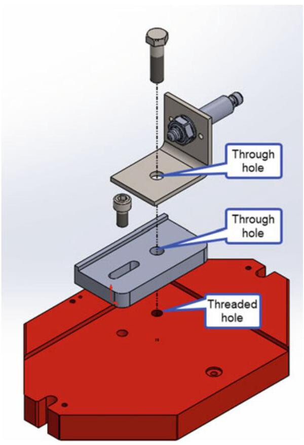
Fig. 5.16 A fixed fastener assembly: the designer has the goal of guaranteeing the correct position of a sensor
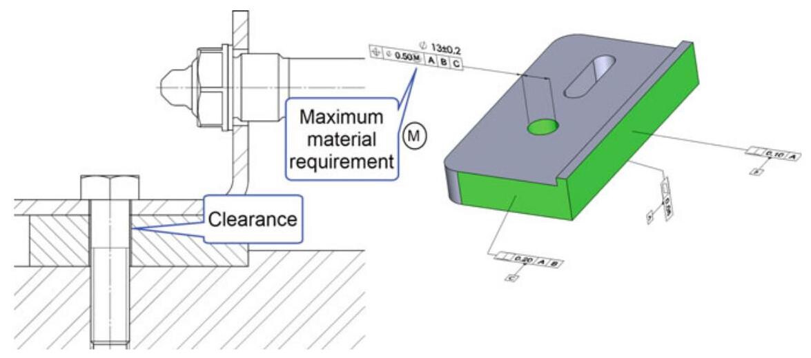
Fig. 5.17 The clearance hole position error does not affect the position of the sensor
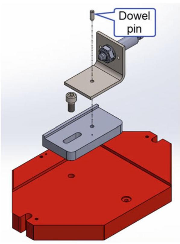
Fig. 5.18 The sensor support is only positioned by means of a dowel pin
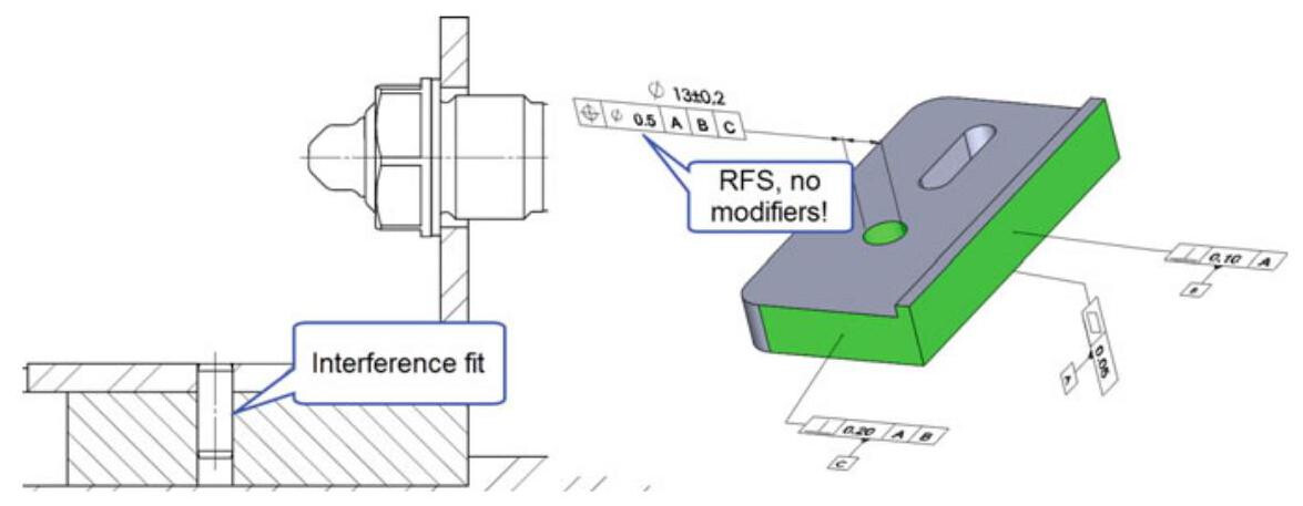
Fig. 5.19 A dowel pin which provides a mating with only a slight interference with the plate. The error in locating the hole in the plate will affect the position of the sensor, and it is therefore better not to further increase the amount of tolerance through the use of an MMR modifier
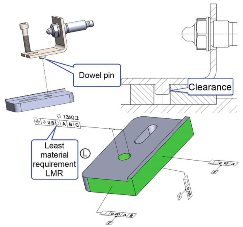
Fig. 5.20 The worst condition that can affect the location of the sensor, occurs when the hole has the maximum allowed dimensions LMS (and when the pin has the minimum allowed diameter, LMS); it is therefore useful to use an LMR modifier
5.4 The MMR and LMR Requirements in the ASME Standards
The ASME standard does not use the term “requirement” to specify an interdependence between size and geometric tolerance, but, depending on its function, the form deviation of a feature of size is always controlled by its size and any applicable geometric tolerances.
In the ASME Y14.5:2018 standard, the modifiers M and L are introduced in Sect. 5.9 through Rule #2: “RFS is the default condition for geometric tolerance values. The Maximum Material Condition (MMC) or Least Material Condition (LMC) modifier may be applied to a geometric tolerance value to override the RFS default”.
The concept of Maximum Material Condition (MMC) or Least Material Condition (LMC) is used to describe the size limit of a feature of size at which the part contains the maximum or minimum amount of material. An MMC size limit combined with Rule #1 describes a boundary of perfect form at the MMC.
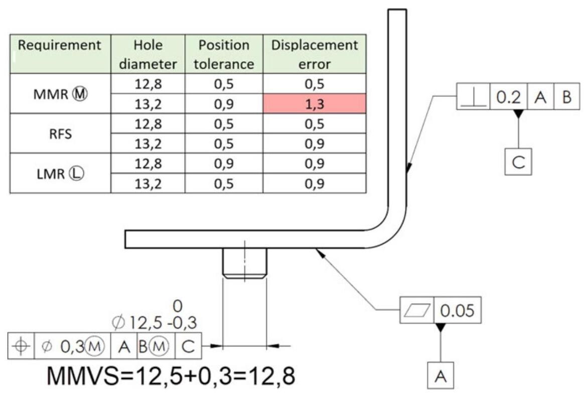
Fig. 5.21 If an MMVS mating pin size of 12.8 mm is assumed and a sensor position error of less than 1mm is accepted,then the LMR requirement guarantees the minimum position error and the maximum admissible tolerance
In the GD&T language, a set of symbols, called “modifiers”, is used to communicate additional information about the drawing or tolerancing of a part. The MMC Mor LMC Cmaterial condition modifier may be applied to a geometric tolerance value to override the RFS default.
However, the ASME standard distinguishes the MMC (or LMC) specification applied to a feature of size from the MMB (Maximum Material Boundary) (or Least Material Boundary, LMB) specification applied to each datum feature reference.
MMB is the worst-case boundary that exists on or outside the material of a feature(s) and it is obtained as a result of the combined effects of size and geometric tolerances.
LMB is the worst-case boundary that exists on or inside the material of a feature(s) and it is obtained as a result of the combined effects of size and geometric tolerances.
RFS is the default condition for geometric tolerance values, while RMB (Regardless Material Boundary) is the default condition for a datum. An MMB or LMB material boundary modifier may be applied to a datum feature reference to override an RMB default.
Consistently with the ISO specification (see Table 5.1), circular run-out, total run-out and orientation tolerances applied to a surface, profile of a line, profile of a surface, circularity or cylindricity cannot be modified to apply an MMC or LMC.
When a geometric tolerance, applied to a feature of size, is specified with an MMC or LMC modifier, a constant boundary (named Virtual Condition, VC) is generated from the collective effects of the MMC or LMC modifier and the geometric tolerance of that material condition. This virtual condition (or Worst-Case Boundary, WCB) is the extreme boundary that represents the worst-case for such functional requirements, such as clearance, assembly with a mating part, thin wall conservation or hole alignment.
Table 5.1 Applicability of MMR or LMR with the various characteristic geometrical symbols
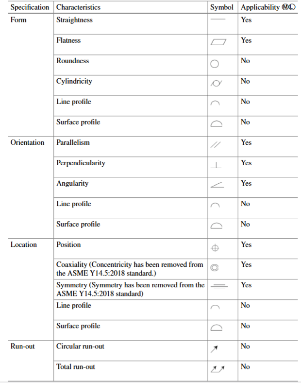
Figure 5.22 shows the collective effects of MMC and the applicable tolerances. The increase in size of the position tolerance zone in the table is commonly referred to as “bonus tolerance” in ASME and is viewed by many to be “extra tolerance for free”.
Figure 5.23 illustrates the concept of inner boundary, a worst-case boundary generated from the collective effects of the smallest feature of size (MMC for an internal feature of size, LMC for an external feature of size) and the applicable geometric tolerance. An outer boundary is a worst-case boundary generated from the collective effects of the largest feature of size (LMC for an internal feature of size, MMC for an external feature of size) and the applicable geometric tolerance.
The resultant condition (RC) is the single worst-case boundary generated from the collective effects of a specified MMC or LMC of a feature of size, the geometric tolerance of that material condition, the size tolerance, and the additional geometric tolerance derived from the departure of the feature from its specified material condition.
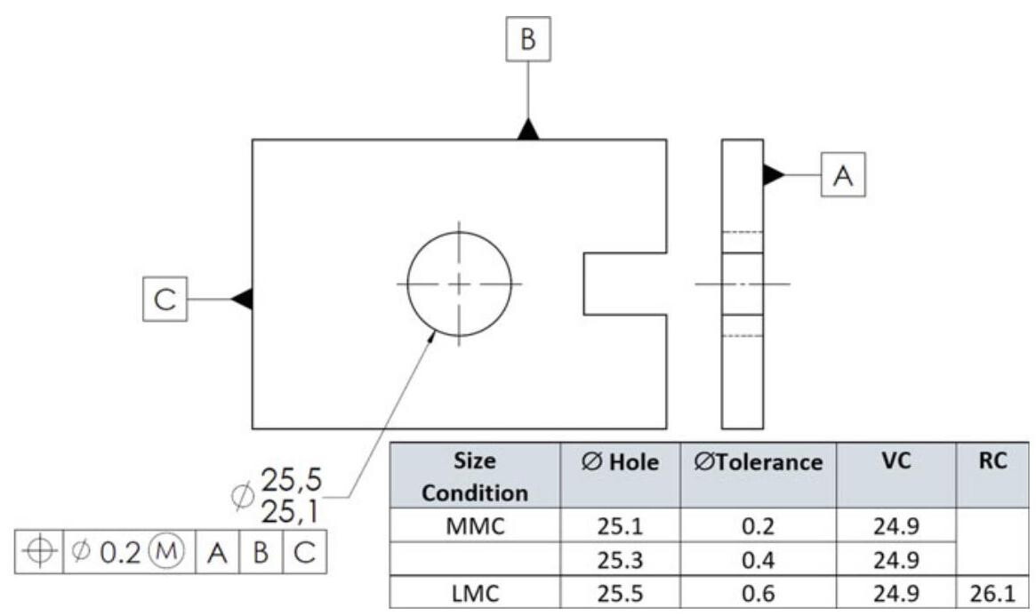
Fig. 5.22 Collective effects of MMC and applicable tolerances. The increase in size of the position tolerance zone in the table is commonly referred to as “bonus tolerance” in ASME
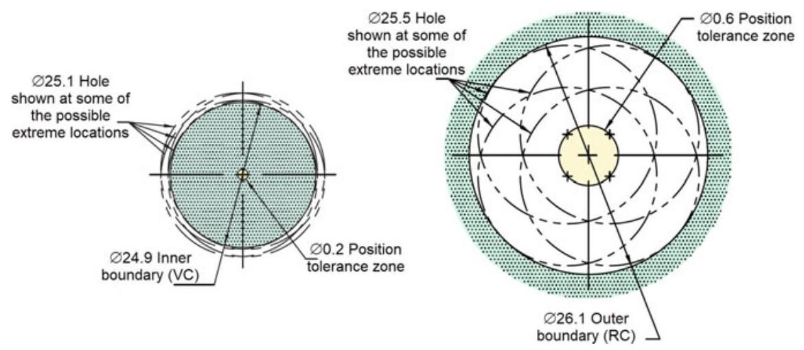
Fig. 5.23 Virtual and Resultant Condition Boundaries for an internal feature, using an MMC modifier
Figures 5.24 and 5.25 show the same concepts applied to an external feature, that is, a plate with two pins. By using the inner and outer boundary values, it is possible to calculate the minimum and maximum distances between the two pins measured with a gauge (Fig. 5.26).
As seen in the ISO standard, in cases where the MMB or LMB boundary is not clear, or another boundary is required, the value of a fixed-size boundary can be indicated, enclosed in brackets, following the applicable datum feature reference and any modifier (Fig. 5.27).
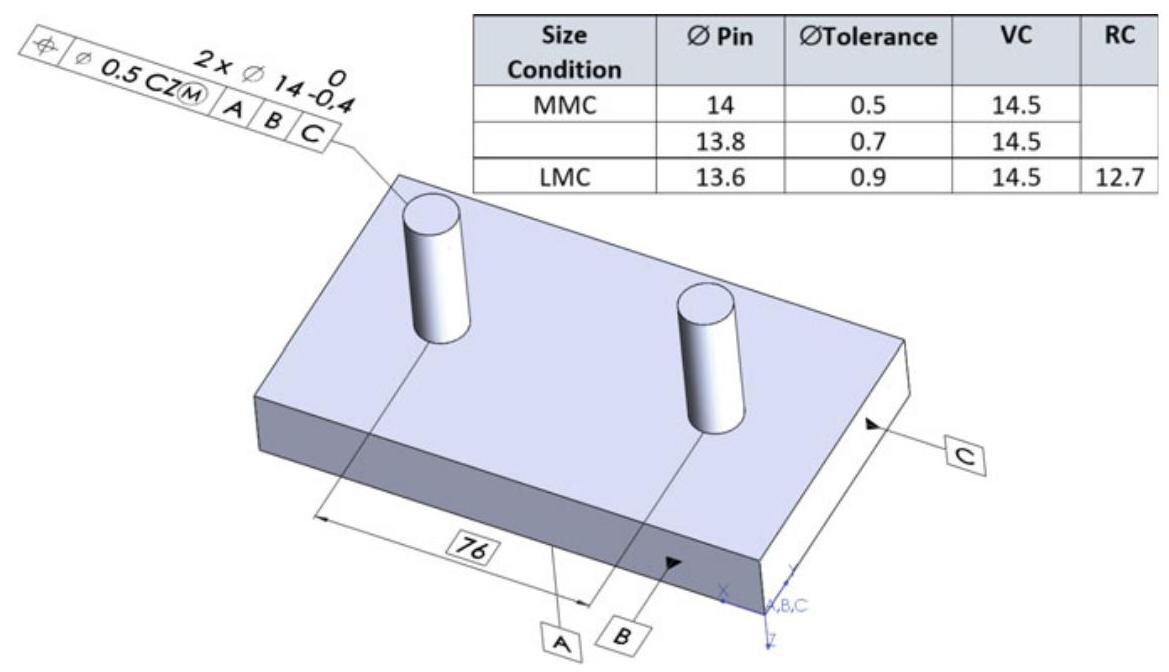
Fig. 5.24 Collective effects of MMC and the applicable tolerances for an external feature
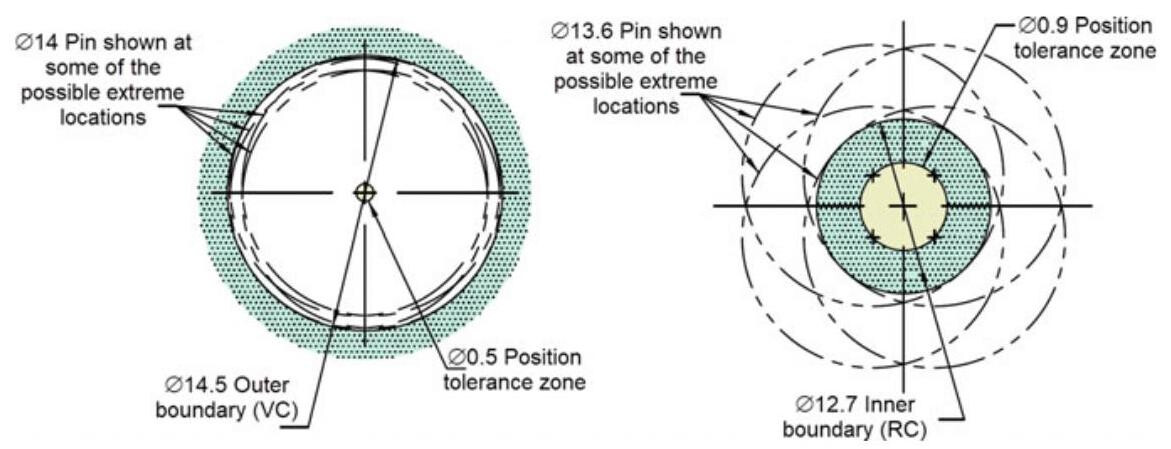
Fig. 5.25 Virtual and Resultant Condition Boundaries for an external feature, using an MMC modifier
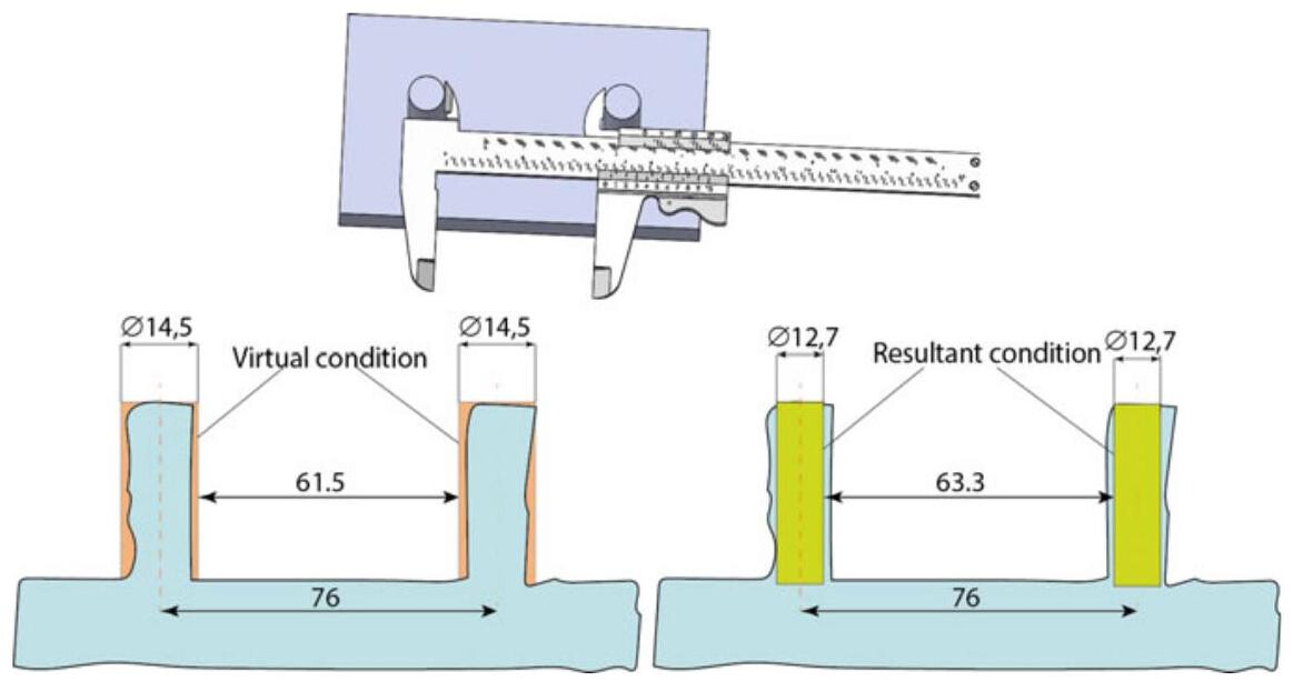
Fig. 5.26 By using the inner and outer boundary values, it is possible to calculate the minimum and maximum distances between the two pins measured with a gauge
Table 5.1 shows whether it is possible or not, to use MMR or LMR with the various characteristic geometrical symbols. These rules are in force in both the ISO and ASME standards.
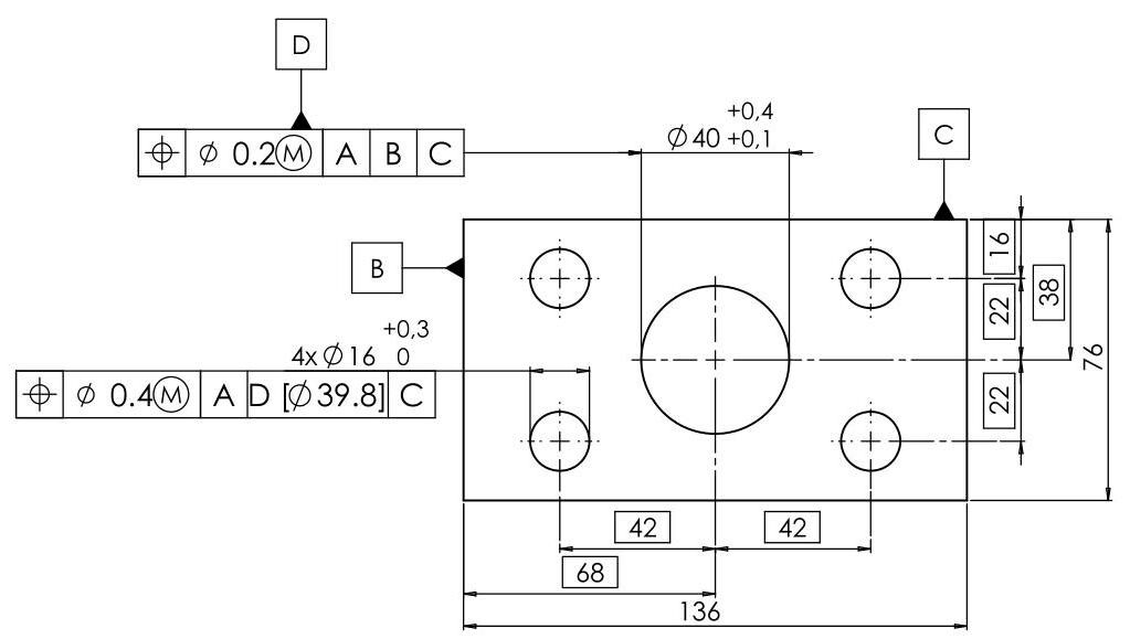
Fig. 5.27 Explicit Specification of True Geometric Counterpart Boundaries in the ASME standard