Abstract This chapter is focused on the main differences between the ISO and ASME standards in the geometrical specification domain of the industrial products, and it starts with details on the historical evolution of the two standards. The main principles of the ISO GPS and ASME GD&T standards, such as the principle of independence and the envelope requirement, are illustrated. Designers are recommended to always indicate the reference standard in the technical drawings of companies, as the interpretation of drawing specifications and the relative inspection may lead to two different results. Finally, the main novelties of the new ASME Y14.5:2018 standard and the new ISO 22081 standard on general tolerances are shown.
4.1 Historical Evolution of the ISO and ASME Standards
The current industrial situation is characterised more and more by a continuous evolution towards increasingly dynamic interaction models between clients and suppliers that put traditional technical communication methodologies under greater pressure.
An always increasing requirement of accuracy in the description and in the interpretation of the functional requirements, and consequently in the drawing up of the technical designs and documents in the mechanical subcontracting sector, which are coherent and complete and able to adequately support the co-design and outsourcing requirements of a production, has been observed.
For this reason, a remarkable effort is under way to develop a coherent and innovative management scheme of geometric tolerances, in order to obtain a better definition of the correlation between the functional requirements, geometrical specifications and relative control procedures, which can be summarised as the Geometrical Product Specification—GPS and Geometric Dimensioning and Tolerancing – GD&T principles, and which, if implemented correctly and coherently, allow the drawbacks of the present methodologies to be overcome and intra and inter-company communication to be revolutionised.
The GPS and GD&T methodologies have evolved according to two basically different approaches (Fig. 4.1). A single standard was developed in the ASME standard, at the end of the 1960’s, to define the fundamental regulations for functional dimensioning. The objective was that of creating a clearly defined and coherent normative system, which gave rise to the ASME Y14.5 standards of 1994 and 2009, and the ASME Y14.5 standard of 2018.
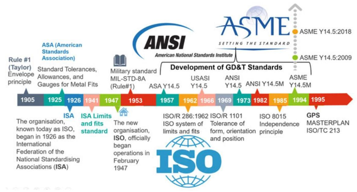
Fig. 4.1 Historical evolution of the ASME and ISO standards on geometrical tolerance
4.1.1 The Birth of Tolerances
The world’s first tolerance standard of limits and fits made use of by industry was published in 1902 in the United Kingdom by the Newall Engineering Co.. In 1901, the UK established the world’s first standardisation organization, the Engineering Standards Committee (which, in 1931, became the British Standards Institution, BSI) and which issued its first standard on limits and fits in 1906. This standard involved the use of a standard sized shaft with various sizes of holes to establish the various types of fit. The standard, which was not initially regarded favourably by industry, since it was based on a shaft basis, was revised in 1924 on basis of the holes.
In the United States, five engineering societies and three government agencies founded the American Engineering Standards Committee (AESC) in 1918, which then became the American Standards Association (ASA) in 1928 and which was reorganised as the United States of America Standards Institute (USASI) in 1966. Finally, the USASI became the American National Standards Institute (ANSI) in 1969. The first standard on limits and fits was the American Tentative Standard Tolerances, Allowances, and Gages for Metal Fits, B4a-1925 which contained tables that listed eight series of fits between holes and shafts, each fit being specified by the limits of size for each of the two mating parts.
The International Federation of the National Standardizing Associations (or International Standards Association, ISA), was established in 1926, and one of the earliest projects was the development of an international system of limits and fits, which was published in 1941 as “ISA Tolerance System” with all the data in metric units. Several European countries adopted this system as the basis of their national standards.
After the conclusion of World War II, a new organisation, the United Nations Standards Coordinating Committee (UNSCC), was established by the United States, Great Britain and Canada to extend the benefits of standardisation to the work of reconstruction. In October 1946, ISA and UNSCC delegates from 25 countries met in London and agreed to join forces to create the new International Organisation for Standardisation (ISO). The new organisation, ISO, officially began operations in February 1947 with its first office in Geneva, Switzerland.
In the same period, in the United States the geometrical tolerances language started as a military standard, known as US Army 30-1-7, dated April 15th, 1946, and was then updated as Mil-Std-8 in 1949.
The American Society of Mechanical Engineers (ASME), a non-profit organisation which was founded in 1880, is one of the oldest standards-developing organisa-tions in America. In 1957, ASME published the first dimensioning and tolerancing standard, that is, Y14.5-1957 for ASA. Subsequent revisions of the Y14.5 standard have been published as USASI (Y14.5-1966) and ANSI (Y14.5-1973 and Y14.5-1982).
The revised ASME Y14.5 M-1994 (“M” because metric units were included) was approved as an ASME standard and, after fifteen years, was followed by ASME Y14.5-2009. The current version is ASME Y14.5-2018, and it was released in February 2019. The objectives of each version have been to correct any inconsistencies in the previous edition through the work committees made up of volunteers from academia and industry.
Since its foundation, ISO has developed many standards in the field of geometric tolerances such as the ISO 8015 standard in 1985 (principle of independence) and the ISO 1101 standard in 1969 (form and position tolerances).
In the ISO ambient of the 1990’s, starting from the consideration that 50% of the standards necessary for GD&T dimensioning were not available or were even in contradiction with the other existing standards, the international technical-scientific community was stimulated into searching for a new, more general and richer language, constructed on the basis of rigorous mathematical assumptions, that is, the aforementioned GPS.
In 1993, ISO set up the Joint Harmonisation Group (ISO/TC 3-10-57/JHG), in which the pre-existing technical committees, that is, ISO/TC3 (Surface Texture), ISO/TC10 (Dimensioning and Tolerancing) and ISO/TC57 (Measurement) were joined together in order to prepare a new standard. Between 1993 and 1996, the Joint Harmonisation Group developed the plant philosophy of the new language and, in 1995, the ISO/TR 14638:1995 “Masterplan” document was issued, which contains, among others, the proposal of a new paradigm for the classification of the existing and future standards,starting from the consideration that 50% of the standards necessary for GD&T dimensioning are not available or that they contradict other existing standards.
In 1996, the Joint Harmonisation Group was disbanded in Paris and the ISO/TC 213 technical Committee was set up. Some American representatives of the ASME Y14.5 committee took part in ISO committee meetings until 1999, after which they stopped attending because of controversies connected to the definition of certain geometrical concepts in the two normative systems, which adopt very different approaches, in spite of some apparent analogies.
4.2 The GPS Matrix Model
The objective of the new language was that of expressing and transmitting, in a rigorous formal manner, all the functional requirements of the products, in order to guarantee functionality, reliability, verifiability and interchangeability. GPS is considered as a shared language between worlds that are often separate, that is, the design, production and the control worlds and, for the first time in the history of standards, it compares designers with metrologists. The ISO/TR 14638:1995 Masterplan document, which was issued in 1995 as a summary of the work of the Joint Harmonisation Group, was drawn up to outline the guidelines for ISO/TC 213. In fact, the Masterplan, which was later approved as the Global GPS Standard, ratifies the new paradigm for the classification of GPS standards. The entire system is known as the “GPS Matrix Model”, and it takes on the role of a “container” of the GPS standards by acting as a matrix in which the lines refer to the geometrical properties of the product (for example, the form or location), while the columns represent the links or, in other words, a specific application ambit of the standards in the context of the development cycle of a product, from its conception to its final control (Fig. 4.2).
A table is formed by crossing these dimensions: the GPS matrix, in which each standard is characterised by 2 coordinates (the properties and the production process step). A standard can often refer to more than one property, or to different steps of the production process; it can therefore take up an area of the matrix and not just a single cell. Each standard of the system includes a final attachment with the exact location of the standard in the matrix, which is indicated with a filled dot (Fig. 4.3).
In the new Masterplan outlined in ISO 14638 of 2015, the GPS standards are classified as:
- Fundamental, that is, standards which define the rules and principles that apply to all categories and which occupy all the segments of the matrix (ISO 8015, ISO 14638).
- General, that is, ISO GPS standards that apply to one or more geometrical property categories, and to one or more chain links, but which are fundamental (ISO 1101, ISO 5459).
- Complementary, that is, ISO GPS standards that refer to specific manufacturing processes (for example, turning) or to specific machine elements (for example, bolts).
Table 1 - ISO GPS Standards matrix model
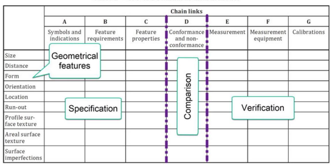
Fig. 4.2 GPS matrix model of the ISO 14638:2015 standard where the lines refer to a specific geometrical feature of the product, while the columns represent the application environments of the standards in the product development cycle context
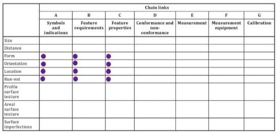
Fig. 4.3 Each standard is characterised by 2 coordinates in the matrix, but can often refer to more than one property, or different steps of the production process, and may thus occupy an area of the matrix rather than just a single compartment, as is the case of ISO 1101 of 2017
The applicability hierarchy was conceived in such a way that the highest standards (general) also apply for the lowest (specific) ones. For example, it is not necessary to specify the reference temperature in ISO 1101 (general, geometrical tolerance) as UNI ISO 1 (fundamental) is valid.
4.3 The Fundamental ISO 8015 Standard
In the 1980’s, the international practices relative to the application of tolerances had, for some time, pointed out the necessity of defining the relationship between dimensional and geometrical tolerances, which had led to an ISO standard in 1985, then transposed by UNI as a national standard, that is, UNI ISO 8015 in 1989, and updated in 2011.
It should be noted that the UNI 7226 standard in the 1973 text defined the relationship between geometrical and dimensional tolerances as: “When only dimensional tolerances are foreseen, all the deviations of form are limited by the dimensional tolerances; in other words, the real surfaces of the objects can deviate from the functional geometrical form as long as they remain within the dimensional tolerances. If the form errors fall within such limits, the form tolerance shall be indicated”.
This concept creates problems if applied to tolerances that can be associated, such as perpendicularity or parallelism, and the section regarding this dependency principle between form and size was eliminated in the revised ISO 1101 standard and consequently in UNI 7226/1.
The “Independency principle” was introduced as a substitute for the aforementioned ISO 8015 standard of 2011, as the fundamental principle for the assignment of tolerances, according to which “Every dimensional or geometrical prescription specified on a design must be respected in itself in an independent way, except when a particular relation is specified”.
Therefore, when no specific indications are given, geometrical tolerances should be applied without taking into consideration the sizes of the element, and its prescriptions (dimensional and geometrical) should be treated as requirements that are independent of each other. In this way, deviations of form are no longer limited by the dimensional tolerances.
In this context, let us consider the shaft shown in Fig. 4.4; apart from the dimensional tolerance on the 50mm diameter, a roundness tolerance appears in a tolerance indicator. As the geometrical tolerances are no longer constrained to the dimensional ones, the shaft may have a lobed form inside the round tolerance, where all the sections are under a condition in which all the sections have the maximum dimension permitted for such a dimensional tolerance. In the worst case, the virtual size (mating size) amounts to 50.02 mm (50 + 0.02).
According to ISO 8015 of 1989, the drawing for which the independency principle is applied should be appropriately identified in order to avoid confusion with the previous designs. Moreover, they should report the following indication:
TOLERANCING ISO 8015
The ISO 8015 standard of 2011 reaffirms the independency principle, and even clarifies that, by default, each GPS prescription pertaining to a feature or to a relationship between a feature and a component should be considered completely independent of other specifications, except in the case in which modifiers such as M and E are used.
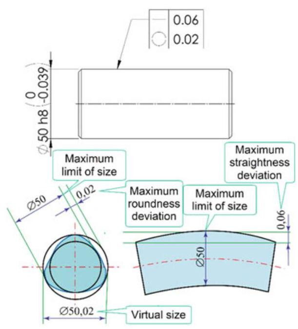
Fig. 4.4 Interpretation of a drawing according to ISO 8015: a lobed form may appear within a round tolerance in a shaft where all the sections are under a condition in which all the sections have the maximum dimension permitted by the dimensional tolerance. In the worst case, the virtual size (mating size) amounts to 50.02mm(50+0.02). It should be noted that the straightness tolerance (0.06) is greater than the dimensional one (0.039)
This means that, in order to indicate the application of the independency principle, it is no longer necessary to indicate the words “Tolerancing ISO 8015” in correspondence to the title block of a drawing. As many GPS symbols are identical to the GD&T symbols of the ASME standards, it would be convenient, to avoid confusion, to write the following in the title block:
ISO 8015 or TOLERANCING ISO 8015
The “ISO default GPS specification” concept, which is defined by the ISO standard, and the “altered default GPS specification” concept, which is a GPS specification that is defined by other standards, are also introduced.
In the latter case, the standards recommend indicating the use of a non-GPS standard in the drawing, in order to make the interpretation clear and unambiguous.
The indication should therefore foresee (Fig. 4.5):
- the word “Tolerancing” or “Tolerancing ISO 8015”;
- the AD symbol that indicates “altered default”;
indication of the non-ISO GPS standard that is considered, including the date of emission.
For example, in the case in which the ASME Y14.5 standard of 2009 is used, the wording should be:
Tolerancing ISO 8015 ASME (AD Y14.5:2009
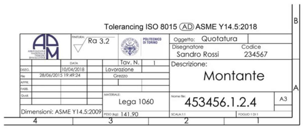
Fig. 4.5 Indication of a specific GPS that is different from the ISO one
4.3.1 The Effect of ISO 8015 on Technical Documentation
In the case where it is necessary to indicate the previous versions of such GPS specifications, it is necessary to specify them unambiguously, i.e. “TOLERANCING ISO 8015:1985” instead of “TOLERANCING ISO 8015”. This will be necessary in situations where an old drawing has been revised and this drawing is now valid with the respective modifications, although not updated in the subsequent GPS standards.
In fact, the second edition of the ISO 8015 standard of 2011 represents a real revolution of the concepts expressed in the previous 1985 edition and defines a real temporal barrier between the drawings conceived before and after 2011 (Fig. 4.6).
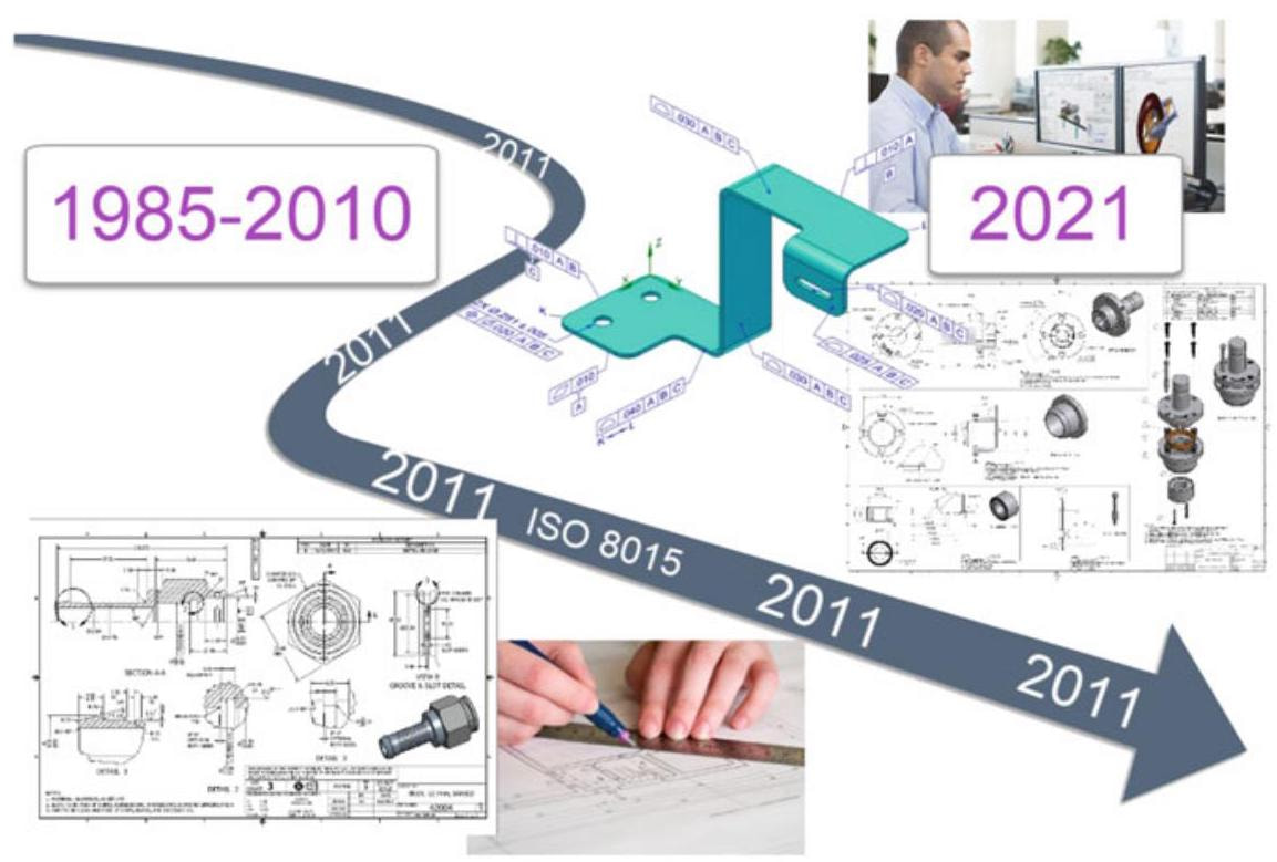
Fig. 4.6 The second edition of the ISO 8015 standard of 2011 represents a revolution of the concepts expressed in the previous 1985 edition and defines a real temporal barrier between the drawings conceived before and after 2011
Principle 5.1 of the standard (the Invocation principle) stipulates that “Once a portion of the ISO GPS system is invoked in mechanical engineering product documentation, the entire ISO GPS system is invoked, unless otherwise indicated on the documentation”, that is, a single reference of the GPS language (such as, for example, a dimension indicated with 30H7) invokes the entire GPS system (unless otherwise indicated).
When the GPS system is invoked, there is a series of consequences, including:
-
All the principles of ISO 8015 are applied;
-
The normal reference temperature is fixed by ISO 1 as {20}^{ \circ }\mathrm{C} .
Figure 4.7 shows a drawing drawn up in 2001, for which ISO 8015, not being explicitly cited, the envelop requirement holds, that is, the perfect (geometrically ideal) envelope with the maximum material size of the dimensional tolerance interval (which also represents the worst mating conditions) .
The same drawing, released in 2012 (Fig. 4.8), should be interpreted in a rigorously different manner. The ISO 8015 standard is a default standard, and there is therefore no need to indicate it.
The drawing invokes the two general ISO 1302 and ISO 13715 standards and consequently the entire GPS system holds.
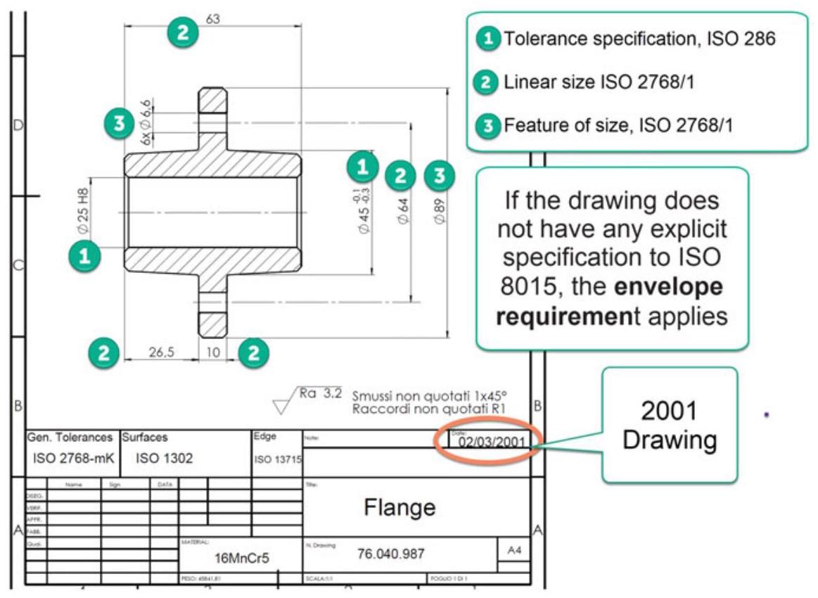
Fig. 4.7 Drawing prepared in 2001, in which ISO 8015 of 1985, not being explicitly cited, the envelope principle holds, that is, the perfect (geometrically ideal) envelope with the maximum material size of the dimensional tolerance interval, which also represents the worst mating condition
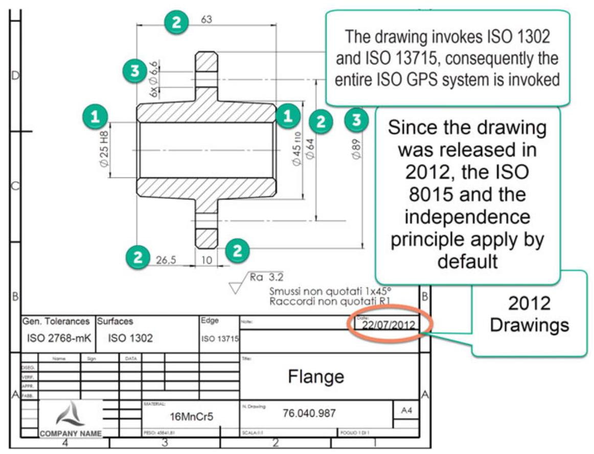
Fig. 4.8 The same drawing as before, but this time conceived in 2012, should be interpreted in a rigorously different manner: ISO 8015 is a default standard, and it is therefore not necessary to indicate it. The design invokes the two general standards, that is, ISO 1302 and ISO 13715, and consequently the entire GPS system holds
-
The dimensions indicated with number 1 recall ISO 286-1:2010.
-
The other dimensions recall 14405-1:2016, and the control therefore involves the distance between two points (local size, default).
-
The independency principle is applied, that is, the worst mating dimension is not that of the maximum material.
The 25H8 dimension in Fig. 4.9 has a tolerance size of 33μm ,while its maximum material limit (minimum size) amounts to 25mm . When referring to 2768-K,the deviation of the cylinder from roundness may be equal to the tolerance of size, that is, 33μm . In the worst case,the virtual size (mating size) amounts to 24.967mm (25-0.033). What advice can be given to designers to avoid this problem? In order to avoid the application of the independency principle, the envelope principle can be suggested with the general indication: Linear sizes ISO 14405
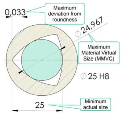
Fig. 4.9 Consequences of the independency principle, which could lead to judicial disputes with the suppliers: the Ø25 H8 dimension has a tolerance of 33μm and a maximum material dimension of 25mm . According to ISO 2768-K,the roundness tolerance should be equal to the tolerance,that is,to 33μm . The mating dimension should be equal to 24.967mm(25-0.033mm)
4.3.2 The Main Concepts Defined in ISO 8015:2011
Other important concepts that are defined in the ISO 8015 standard of 2011 are:
- Fundamental assumptions for the reading of specifications on drawings (Sect. 4):
(a) Functional limits (Sect. 4.2), based on experimental and/or theoretical investigations, and which are known with no uncertainty. The choice of the designer, pertaining to defining the limits within which the overall functionality is reached, can never be justified.
(b) Tolerance limits (Sect. 4.3), which are identical to the functional limits, which means the designer has the responsibility of indicating the functional limits on the drawing through the tolerance limits.
(c) Workpiece functional level (Sect. 4.4), which means that the workpiece should function 100% within the tolerance limits and 0% outside the tolerance limits.
- Definitive drawing principle (Sect. 5.3): if not indicated, the specifications are applied to the final stage of the product, as designed, but intermediate production stages can also be indicated.
- Feature principle (Sect. 5.4): a workpiece should be considered to be made up of several features limited by natural boundaries. Each and every GPS specification of a feature or relationship between features applies by default to the entire feature or features; each GPS specification applies only to one feature or one relation between features. Indications which specify that a requirement applies to more than one feature, e.g. when the CZ(combined tolerance zone) indication is used, are available.
- Independency principle (Sect. 5.5): each and every GPS specification of a feature or relation between features should by default be fulfilled independently of any other specifications, except when a special indication is specified (e.g. (C), C(C), CZ modifiers)
- Default principle (Sect. 5.7): each specific GPS invokes a series of rules that were pre-defined in other standards (default). A rule (the most common) is univocally pre-defined in the GPS system, and it can be omitted from the drawing in order to prevent overloading it. Pre-defined rules can be left out from the drawing by introducing symbols or others (modifiers) defined in the GPS system or even personalised within a company. For example, a 30H6 dimensioned hole (ISO 286-2) should defer to the definition of the tolerance of a diameter of a hole of between 30 and 30.016. As nothing else is specified, the diameter measured as the distance between two points is considered valid (ISO 14405-1).
- Reference condition principle (Sect. 5.8): all GPS specifications apply by default for a standard reference temperature of 20℃ ,as defined in ISO 1,and the workpiece should be free of contaminants.
- Rigid workpiece principle (Sect. 5.9): each component is considered as an infinite rigid body that is not affected by any external force. A workpiece should by default be considered as having infinite stiffness, and all GPS specifications apply in the free state, and as undeformed by any external forces, including the force of gravity. A rigid body is a component that does not deform or bend by a quantity that prevents it from functioning under the effects of forces and/or the mounting constraints. Mention is also made of free state, that is, all the dimensions and the specified tolerances are applied without the action of any force other than gravity. When the workpiece is flexible, this should be indicated on the design (ISO 10579-NR).
- Duality principle (Sect. 5.10): the ISO GPS standards express duality between the specification and the verification. Everything that is done in the specification process is reflected in the actual measurement process. The procedure that allows the description of the product to be made in the design and control phases is the same as it utilises the same type of operators.
- General specification principle (Sect. 5.12). General tolerances can be indicated on the design by means of references to the specific standard (e.g. ISO 2768/1) in the title block. These references are applied to each characteristic of each feature or relationship, unless a specific tolerance, which prevails, is indicated. More than one general tolerance can be present, on condition that it is clearly indicated to what each one refers. In the case of conflict, the most permissive prevails.
4.4 General Geometric Tolerances
All the features of a product always have a dimension and a geometrical form; since the functional requirements state that the dimensional deviations and the geometrical deviations should be defined and limited, the drawings should be completed with all the necessary tolerances. However, considering that the geometric tolerances are no longer limited by size tolerances, as a result of the introduction of the independency principle, they should all be indicated on a drawing, which in turn would then be overloaded with too many indications and therefore not so easy to interpret.
Table 4.1 General tolerances according to ISO 2768/2
It should be recalled that ISO 2768/1 indicates the general dimensional, linear and angular tolerances,which are grouped together in the f, m, c and v precision classes.
The ISO 2768/2 standard of 1989 had the purpose of simplifying drawing indications and of specifying general geometrical tolerances in order to control those features on a drawing that do not have any respective individual indications. It divides general geometrical tolerances into three tolerance classes ( H, K and L , in decreasing precision), thereby allowing the geometrical specifications and the reading of the drawings to be simplified, and at the same time facilitating the choice of the tolerances.
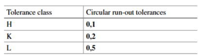
Table 4.1 shows the values of the general tolerances of a circular run-out, which can also be used for roundness. As no specific values are foreseen in the standard for the roundness tolerance, it is made equal, in numerical value, to the dimensional tolerance on the corresponding diameter (Fig. 4.10), but with the constraint of not exceeding the value of the circular radial run-out, which is instead specified in the standard.
The ISO 2768/2 standard was replaced by the ISO 22081 standard, since it is possible that the general geometrical tolerance indication can make it difficult to interpret the errors and the relative control phase:
- The standard only prescribes the tolerances values of straightness, flatness, perpendicularity, symmetry and circular run-out.
- It should be pointed out that the general tolerances do not control the cylindricity, angularity, coaxiality, profile, positional tolerance or total run-out tolerances.
- Let us consider the same figure that is reported in the ISO 2768/2 standard (Fig. 4.11). A great stretch of imagination is necessary to ascertain that, interpreting the general quality tolerances H, it is possible to define a datum C (hole axis) with respect to which the perpendicularity errors of the two milled faces are specified.
- The general tolerances indicate orientation errors, but without establishing the datum.
- Another error is that of the definition of the general angular error (by using the ISO 2768/1 standard, as shown for the workpiece indicated in Fig. 4.12). Should the workpiece be placed on its largest or smallest side in order to perform a control? The tolerance zone in fact becomes larger and larger as the distance from the datum feature increases.
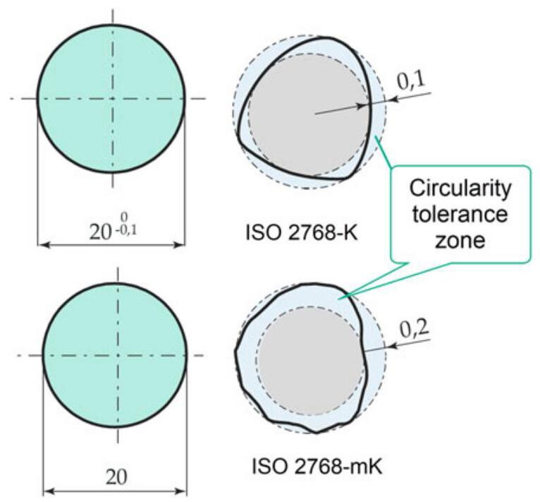
Fig. 4.10 The permitted deviation of the diameter is indicated directly on the drawing; the general circularity tolerance is equal to the numerical value of the diameter tolerance but it is subject to the constraint of not exceeding the value of the circular radial run-out, which is instead specified in the standard. The general tolerances indicated with the ISO 2768-mK specification apply in the figure below. The deviations permitted for a 20mm diameter are ±0.2mm . These deviations lead to a numerical value of 0.4mm ,which is greater than the value of 0.2mm given in Table 4.1; the value of 0.2mm therefore applies for the circularity tolerance
4.4.1 The New ISO 22081 Standard
The new standard outlines rules pertaining to the definition and interpretation of general specifications defined according to ISO 8015 (general tolerancing) which are applicable to the whole workpiece.
The general geometrical and dimensional specifications can be applied to integral surfaces (not integral lines), according to the following rules:
(a) The general dimensional specifications are applied to features of size, that is linear size (according to ISO 14405-1) and angular size (according to ISO 14405-3).
(b) The only general geometrical specification is the surface profile, which is applied to integral features. In this case, a datum system should be specified
The standard emphasises that it is the responsibility of the designer to ensure the complete and unambiguous definition of functional requirements. Moreover, the geometrical features that influence the functions must be defined appropriately and the entire workpiece should be completely specified.
General dimensional specifications are applied to a feature of size that has been identified on a drawing by means of a linear or an angular size which has no individual tolerance and which is not a theoretically exact dimension or an auxiliary dimension (Fig. 4.13).
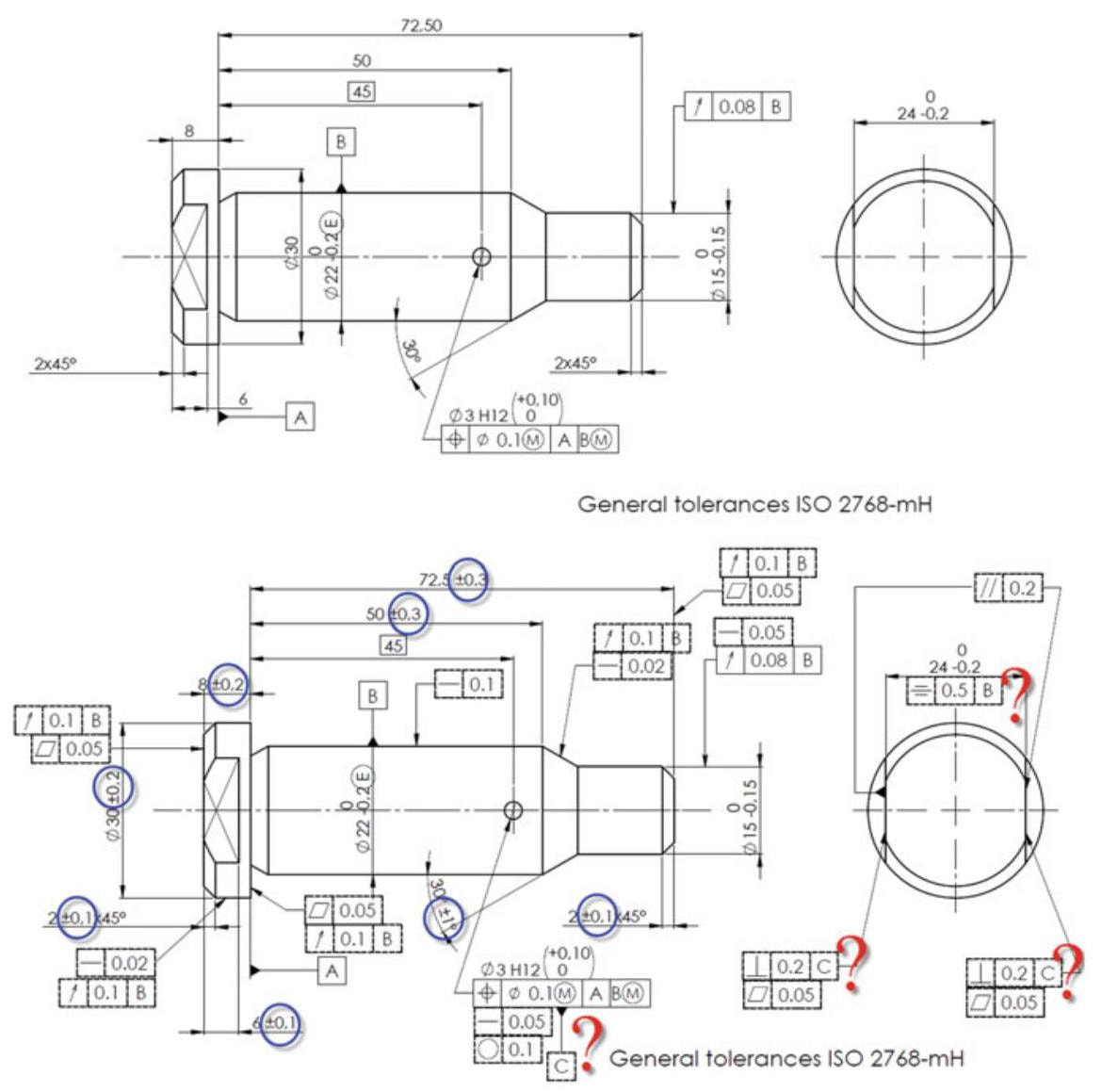
Fig. 4.11 If the figure reported in the ISO 2768/2 standard is taken into consideration, it is possible to demonstrate that the indications of the general tolerances make it difficult to interpret the errors and the relative control phase (the blue circles and the broken-lined frames at the bottom of the figure show the interpretation of the general tolerances). A great effort of imagination is in fact necessary to establish that, interpreting the general tolerances of quality H, it is possible to define a reference C (hole axis) with respect to which the perpendicularity errors of the two milled faces are specified
The general geometrical specification applies to each integral feature on the workpiece, with the following exceptions, see Fig. 4.14:
- it does not apply to any feature of size
- it does not apply to any feature with an individual indicated geometrical specification;
- it does not apply to any datum feature referenced in the datum section of the general geometrical specification.
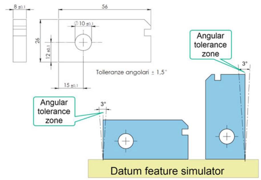
Fig. 4.12 Another error is that of the definition of the general angular error, as shown in the plate above. In order to conduct the control, should the workpiece be placed on its larger or smaller side? The tolerance zone in fact becomes larger and larger as the distance from the datum feature increases
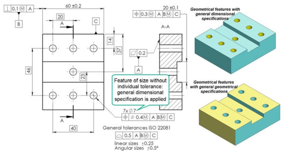
Fig. 4.13 An example of the application of general dimensional and geometrical specifications on integral features
The permissible error for the indication of general dimensional tolerances in technical product documentation can be defined (near the title block) as both a fixed value and as a variable value.
The variable tolerance value should be defined directly by the designer, who should refer directly to a table or a document associated with the drawings (Fig. 4.15).
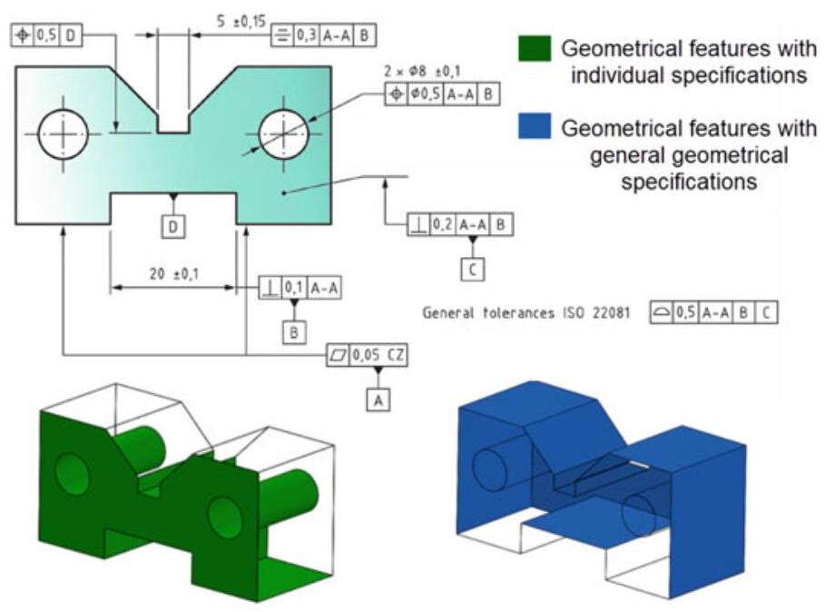
Fig. 4.14 An example of the application of general geometrical specifications to integral features
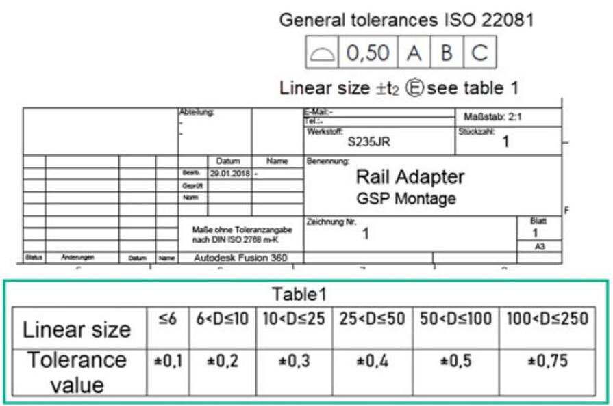
Fig. 4.15 An example of the indications near the title block, with reference to a table on a drawing
4.5 The New ASME Y14.5:2018 Standard
According to many designers, the ASME Y14.5 standard is the clearest and most coherent standard for the technical documentation of a product, because it uses the GD&T language to communicate the intent of a designer in a complete and unambiguous way, thereby allowing components to be obtained with shapes and dimensions that can guarantee the desired assembly, functions, quality and interchangeability.
The new ASME Y14.5:2018 standard is more readable, more detailed and clearer than the previous version (12 sections, 328 pages compared to the 214 pages of the previous ASME Y14.5:2009 standard), and many ambiguities of the previous version have been eliminated, the layout of the standard completely revised and all the sections have been renumbered.
The standard has also been revised in view of the great changes that have taken place in the twenty-first century, with the widespread use of Computer-Aided Design (CAD) and the transition of the industry towards Model Based Definition (MBD) techniques with 3D annotations. From this perspective, the GD&T specifications that were previously introduced on many illustrations have been added to the 3D views of the model.
The 14 classical geometric control symbols have been reduced to 12, since the concentricity and symmetry symbols have been eliminated and replaced by the position symbol. However, this deletion of the symbols does not leave industry without a means of controlling coaxial or symmetrical features, but it does eliminate the confusion that surrounded these symbols because they were often used incorrectly or were misinterpreted.
The sections dedicated to orientation, form and profile tolerances have been completely restructured to obtain a better readability. In particular, the FROM-TO symbol has been added to indicate a specific transition in a non-uniform profile tolerance (Fig. 4.16). Another important change concerns the addition of a new modifier, called “dynamic profile”. This is a small triangular symbol that can be inserted inside the feature control frame after the tolerance value. The function of the dynamic profile is to allow the form to be controlled, independently of size. Finally, run-out tolerance may now be used in an assembly and applied to a tangent plane for one or more coplanar feature faces that are perpendicular to a rotation axis.
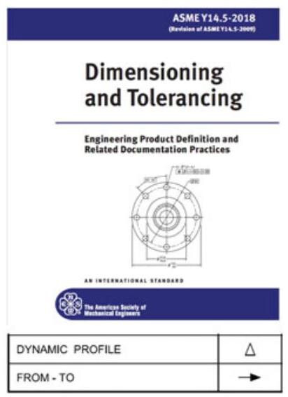
Fig. 4.16 The new ASME Y14.5:2018 standard with the new symbols
4.5.1 The Envelope Requirement or Rule#1 of the ASME Standard
The ASME Y14.5 standard has codified the envelope requirement as Rule#1, whereby “No element of a feature shall extend beyond the Maximum Material Condition (MMC) boundary of perfect form”. The envelope requirement may also be applied with the ISO standards, by means of a circled E symbol, placed next to the tolerance dimension. According to this rule (which is also known as Taylor’s rule), it is stated that where only a tolerance of size is specified, the limits of size of an individual feature of size prescribe the extent to which variations in its geometric form, as well as its size, are allowed. (Fig. 4.17).
The form tolerance increases as the actual size of the feature departs from MMC towards the Least Material Condition (LMC). There is no perfect form boundary requirement for the LMC. When inspecting a feature of size that is controlled by Rule #1, both its size and form need to be verified. If not otherwise specified, the Least Material Condition (LMC) is verified by making a two-point check at various points along the cross section, while the Maximum Material Condition (MMC) is verified by checking that the whole feature falls within a maximum material envelope of perfect form.
According to ASME Y14.5:2018 (Sect. 3.57), the actual local size is the actual value of any individual distance at any cross section of a feature of size. The ASME Y14.5.1M:1994 standard (Mathematical Definitions of Dimensioning and Toler-ancing Principles) provides a further clarification about the local size requirements of Rule #1. The actual local size is defined by continuously expanding and contracting spheres, whose centres are situated on a derived median line (Fig. 4.18).
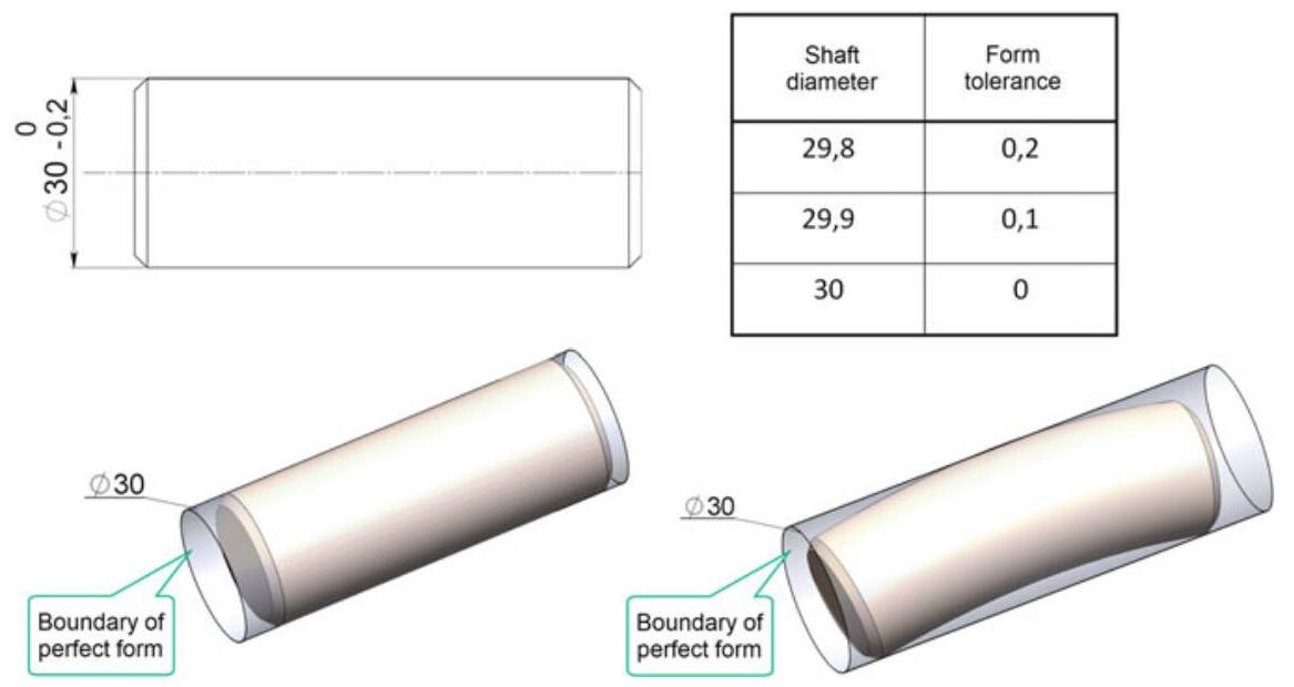
Fig. 4.17 Interpretation of the drawings according to Rule#1 of the ASME Y14.5 standard; the limits in variation of the dimensions and form of a shaft allowed by the envelope principle are visible
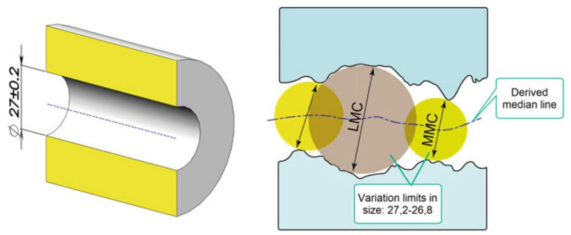
Fig. 4.18 The size of the sphere that may be swept along the derived median line without intersecting the feature boundary determines the actual values of the maximum and least material sizes
Figures 4.19 and 4.20 show the respective control procedures of a hole and a shaft according to Taylor’s principle. If the feature fits inside a gauge which has the same size as the maximum material size, the feature conforms to that tolerance limit. At the same time, if the workpiece is at its maximum material condition (MMC), then it cannot undergo any form variation (i. e. out-of-roundness or straightness of its axis), or it will not fit within the boundary.
Figure 4.21 shows the application of the envelope requirement in the ISO standard, where the use of the symbol E within a circle is necessary. Therefore,when all the local diameters (18mm) of the hole are under the maximum material condition,the form is perfect.
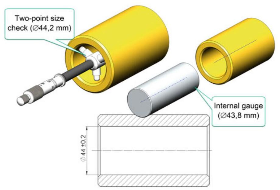
Fig. 4.19 Verification procedure of a hole according to the envelope principle. The minimum material condition is controlled by using an internal gauge (measured between two opposite points), while the maximum material condition is checked by means of a pin with the MMC dimensions
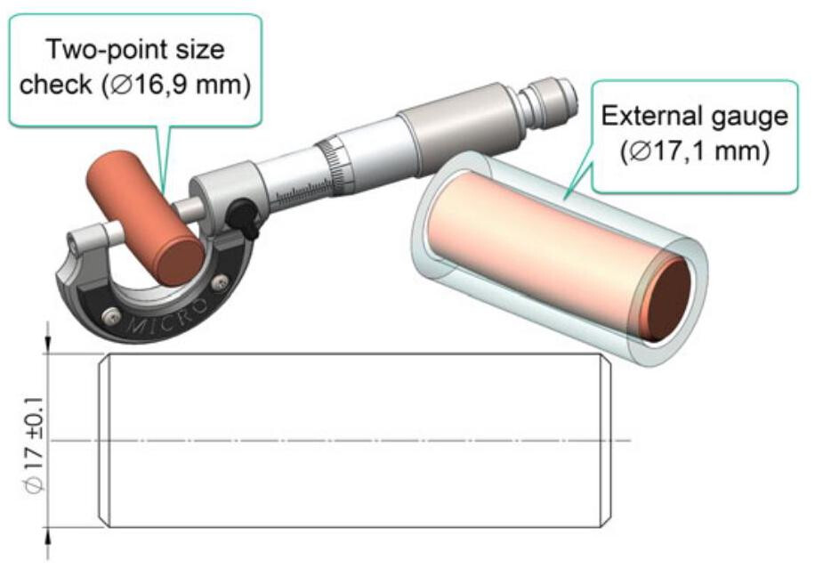
Fig. 4.20 Verification procedure of a shaft according to the envelope principle or ASME Rule#1. The minimum material condition is controlled by using an external gauge (the measurement between two opposite points), while the maximum material condition is checked by means of an envelope of perfect form with MMC dimensions
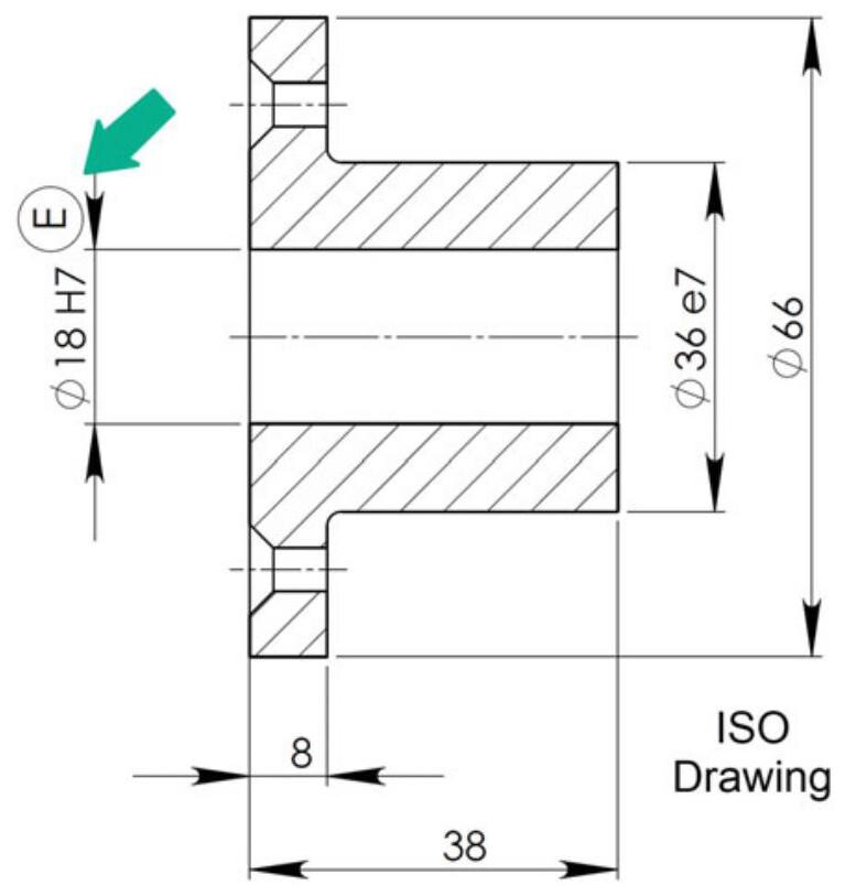
Fig. 4.21 The envelope requirement in the ISO standard is indicated by means of a circled E, which is placed next to the tolerance dimension; the hole has a perfect form when all the local diameters are under the maximum material conditions,that is, 18mm
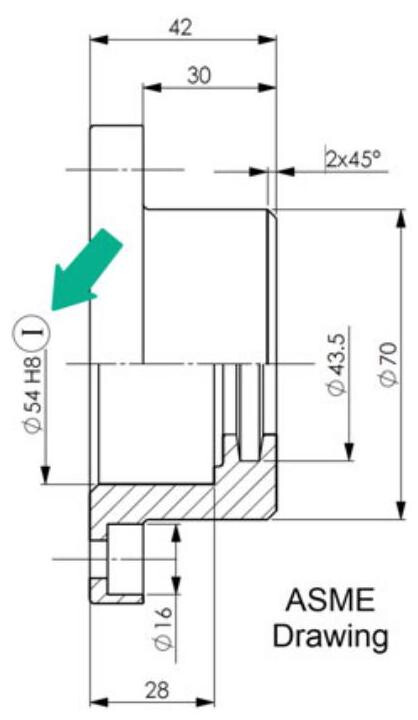
Fig. 4.22 In order to apply the independency principle to ASME drawings, it is necessary to insert the independence symbol (circled I) next to the dimension
This type of dependence between geometrical and dimensional tolerances ultimately implies that the actual local dimensions of the considered feature vary, within the assigned dimensional tolerance field, in order to compensate, with reference to the maximum material dimensions, for any foreseeable form deviations. Such control standards, which are appropriate in the case of mating, may be restrictive for all the other geometrical features, and may make it necessary, in the latter case, to furnish an indication of exception (the ASME standards have introduced the Csymbol, see Fig. 4.22), with the consequence of a source of ambiguity being created as it is not possible to ascertain whether the absence of such an indication depends on the choices of the designer or rather on an oversight within such a complex technical document.
Apart from this problem, the verification of the envelope principle, which requires the use of functional gauges or controls carried out by means of measurement machines that have been set up and evaluated in an adequate way, is not an easy task.
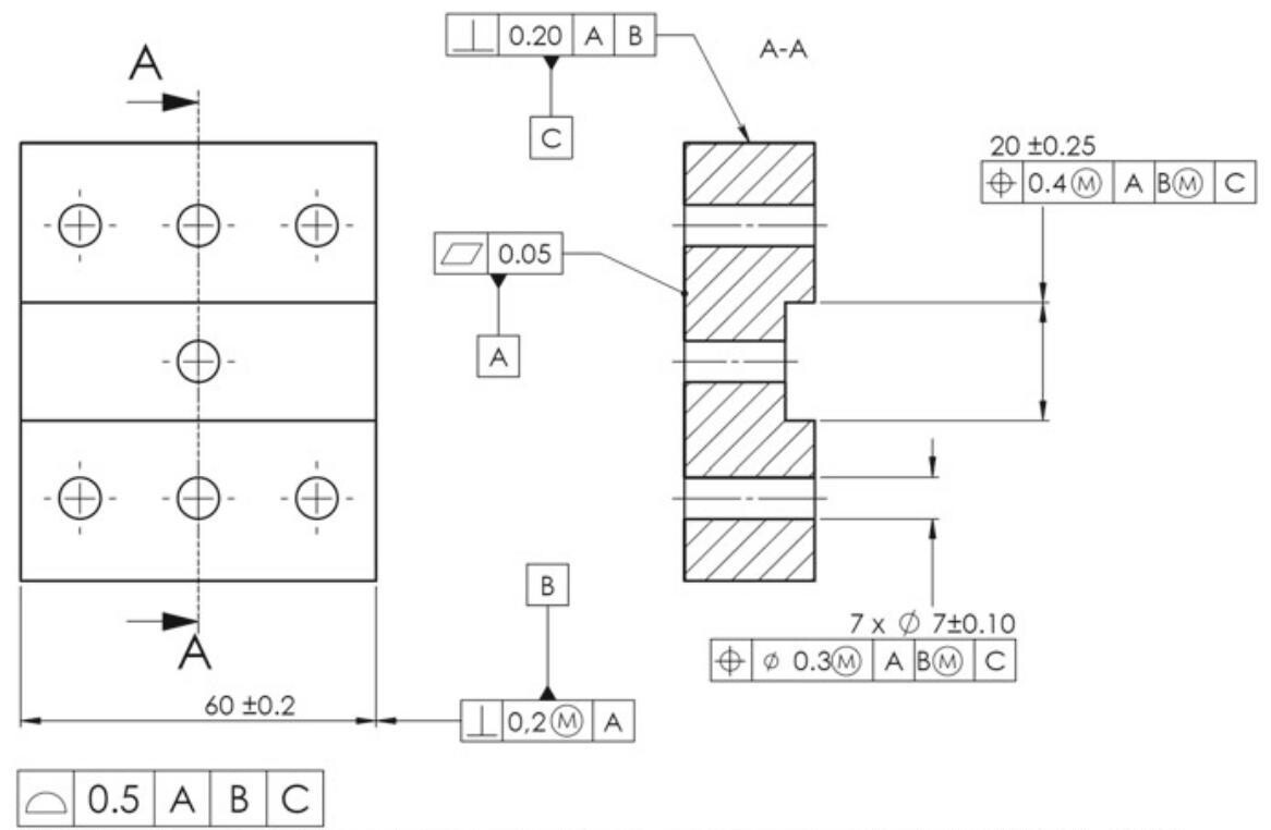
Table 4.2 shows a summary of the main differences between the two principles. It should be pointed out that, in the case of ISO GPS standards, considering that, with the introduction of the independency principle, the form errors are no longer limited by dimensional tolerances, the general geometric tolerances have been introduced to simplify the indications on a drawing.
The ASME Y14.5 standard makes the general tolerance indications redundant, because the envelope principle, which allows the form errors to be limited, is utilised by default. Figure 4.23 shows the potentiality of such a specification, which allows both the dimensional and geometrical general tolerances to be eliminated, thus making the control phase univocal and coherent. Moreover, the tolerance of a profile locates and orients all the surfaces of the workpiece (except the datum features, which have other specific controls [2], see Fig. 4.24).
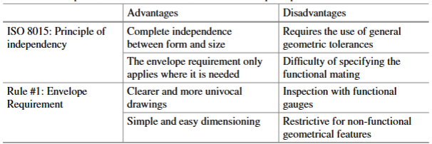
Table 4.2 Comparison of the fundamental ISO and ASME principles
This drawing should be interpreted in accordance with ASME Y14.5-2018 Dimensions not shown on drawing are controlled by means of a 3D CAD file
Fig. 4.23 The ASME Y14.5 standard makes the indications on the general tolerances redundant, as it adopts the envelope principle, which allows the form errors to be limited by default Rule #1
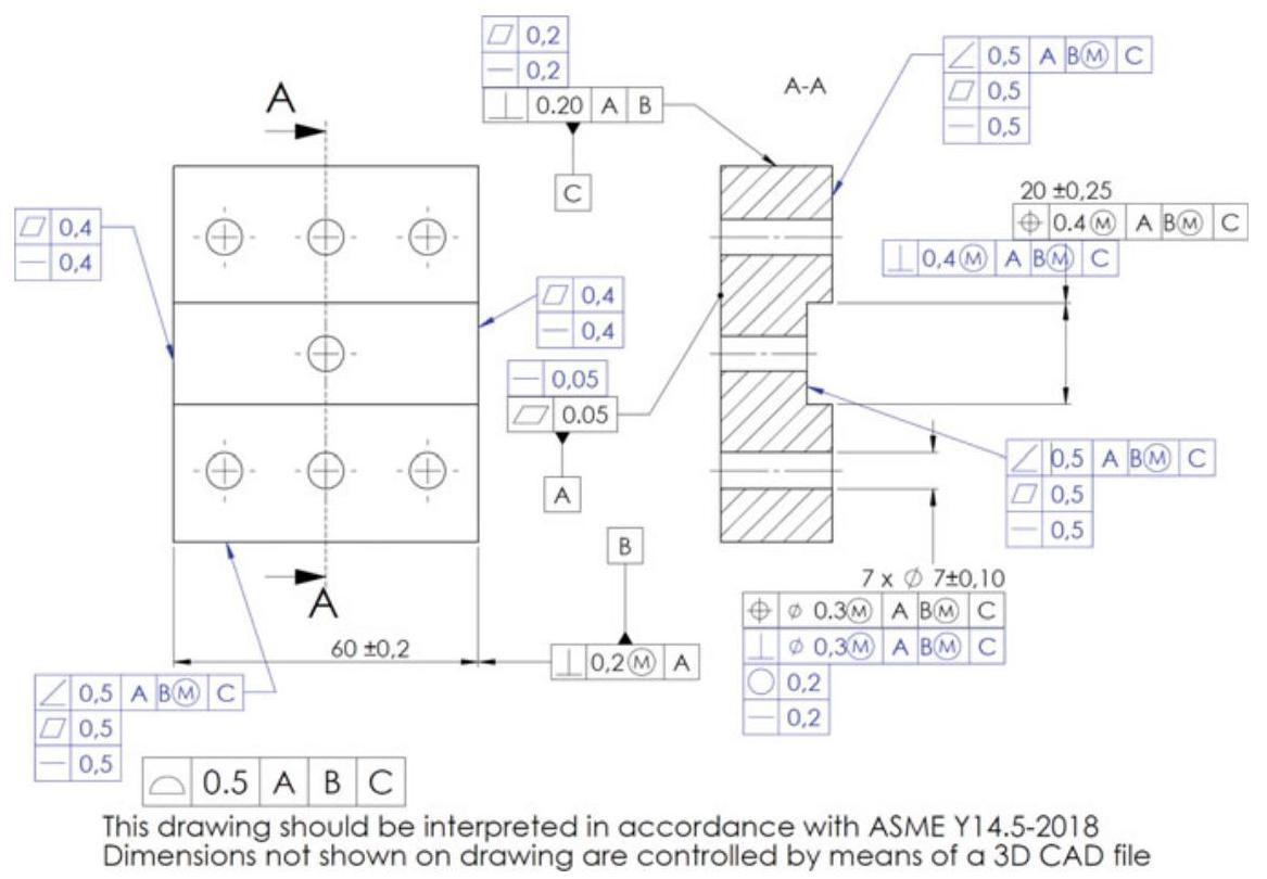
Fig. 4.24 The blue coloured frames show the implicit indications of the drawing and point out the potentiality of the ASME specification, which allows both the dimensional and geometrical general tolerances to be eliminated, thus making the control phase univocal and coherent. The general tolerance on a profile locates and orientates all the surfaces of the workpiece
4.6 The Main Differences Between ISO GPS and ASME GD&T Standards
Today, the importance of international standards in the technical documentation field is growing at the same rate as the globalisation of production; a simple, clear, univocal and concise three-dimensional description of the designed components is therefore necessary.
In light of this, the adoption of the ISO GPS or ASME standard can surely be the right path to follow in response to the specific requirements of each single company, in order to offer an unambiguous normative context, with simple and coherent rules, thus eliminating uncertainties and confusion in the design, manufacturing and verification phases.
It therefore appears opportune to underline the main differences between the ISO GPS and ASME standards [3].
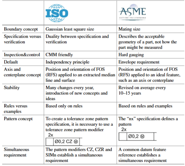
- The main difference between the two standards concerns the concept of interdependence between form and dimension, for which ISO uses the Independency Principle concept by default, while ASME uses the Envelope Requirement (Rule #1, Fig. 4.25).
- A Gaussian dimensioning concept is adopted by default in the ISO standards as a way of specifying the dimension of a feature; in other words, all the points on the surface should fall within an envelope that is obtained by means of the least squares method (this means that some of the points might lie outside a boundary that is defined by the size specification, although it still conforms to the size specification). The mating size concept is instead adopted in the ASME standards to describe the size of a feature, that is, all the points on a surface should fall within an envelope which has the maximum material dimensions (Fig. 4.26).
- The ISO standards express a “duality” between specification and verification. Whatever is done in the specification process is mirrored in the actual measurement process. This is described as the “duality principle”. The ASME standard intentionally distanced itself from the measurement and control process. In fact, in clause 1.6 of ASME Y14.5-2018, the standard states that “This document is not intended as a gaging standard. Any reference to gaging is included for explanatory purposes only. For gaging principles, see ASME Y14.43 Dimensioning and Tolerancing Principles for Gages and Fixtures”. In other words, the ASME standard describes the acceptable geometry of a part, and not how the part might be measured.
- The ISO standard is described as “CMM friendly”, that is, the preferred control system is the coordinate measurement machine. The ideal or nominal geometry is defined in the design process, and the resulting workpiece is the real one in the manufacturing process. The control phase “extracts” the geometry of the physical workpiece in order to elaborate the geometrical features associated with the surfaces (planes, spheres, cylinders) and estimates the value of the measurement of interest (Fig. 2.2). The ASME standard is based on the idea of specifying the geometrically perfect zones within which the real surfaces should be found. This is often referred to as a preference for “hard gauging”, that is, it is possible to construct functional gauges that represent a physical representation of the tolerance zone (Fig. 4.27).
- About 150 distinct standards have been issued in the ISO ambit to define the GPS language,while,since back in the 60s ,only a single standard has been developed to define the fundamental rules for the functional dimensioning of components, with the objective of creating a well-defined and coherent normative system, which gave rise to the ASME Y14.5 standard of 2018 (328 pages, Fig. 4.28).
- Another important difference pertains to the stability of the standards: the ISO standard is in continuous evolution, with many changes, sometimes contradicting the previous standards: starting from 2010, the number of standards has grown enormously. Instead, in the ASME ambit, a new GD&T standard is issued every 10-15 years.
- The tolerances of position and orientation of a feature of size in the ISO standards are applied to an extracted median line and surface, while, in ASME, they are applied to ideal (of derived) features, such as axes and centreplanes. For this reason, it is recommended to always indicate the reference standard in the technical drawings of companies, in that, as can be seen in the case of the parallelism tolerance shown in Fig. 4.29, the control of the error leads to two different results: control of the derived median line in the ISO standards and control of the axis in the ASME standard [4].
- Another non-negligible difference is the use of a comma as the decimal separation in the ISO standards and a dot in the ASME standards (Fig. 4.30).
- Finally, in the ISO standards, use is made indifferently of the control of a location or profile to locate and orientate a surface, while in the ASME standards, the location tolerance is only used for features of size (Fig. 4.31).
Fig. 4.25 The effect of two different default principles as outlined in the ISO and ASME standards. The dimensional and geometrical tolerances in the ISO drawing lead to an extreme boundary condition of 10,4 mm (10 + 0,4) and the roundness error may be greater than the dimensional tolerance. In the ASME drawing, a roundness error is already controlled by the dimensional tolerance, and the use of the roundness control therefore only has the purpose of limiting the error
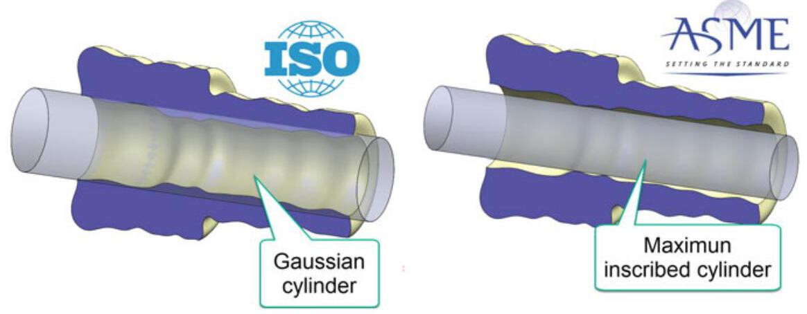
Fig. 4.26 The mating size concept is used in the ASME standards to specify a dimension of a feature (the diameter of the largest inscribed cylinder), while the Gaussian dimensioning concept is utilised in the ISO GPS standards to specify a dimension of a feature
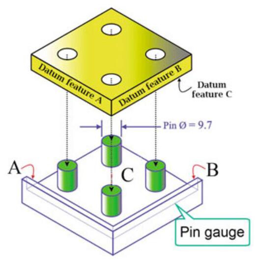
Fig. 4.27 Functional gauge used to verify the location of the 4 holes of a plate; the gauging reproduces the worst mating conditions
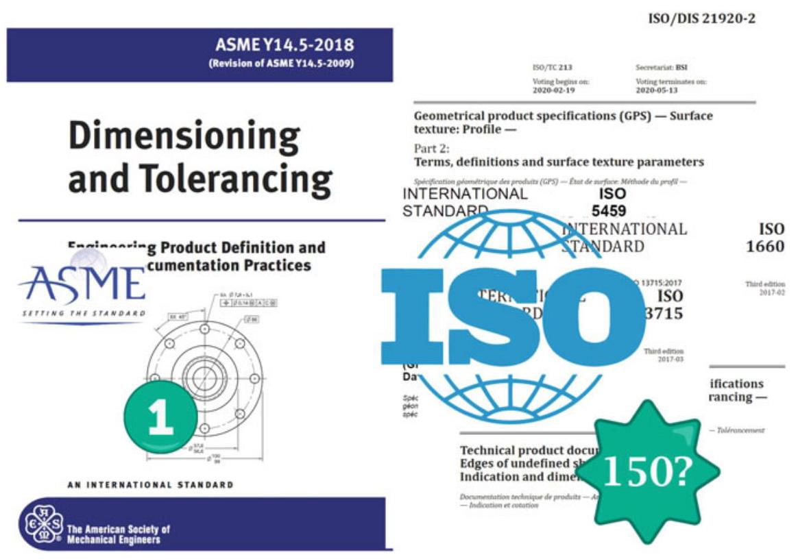
Fig. 4.28 About 150 distinct standards are available in the ISO ambit to define the GPS language, while only a single standard has been developed in the ASME ambit to define the fundamental rules for the functional dimensioning of the components
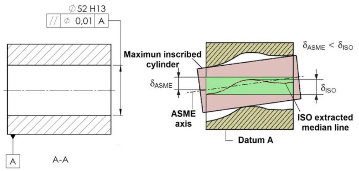
Fig. 4.29 The control of the parallelism tolerance leads to two different results in the ISO and ASME standards
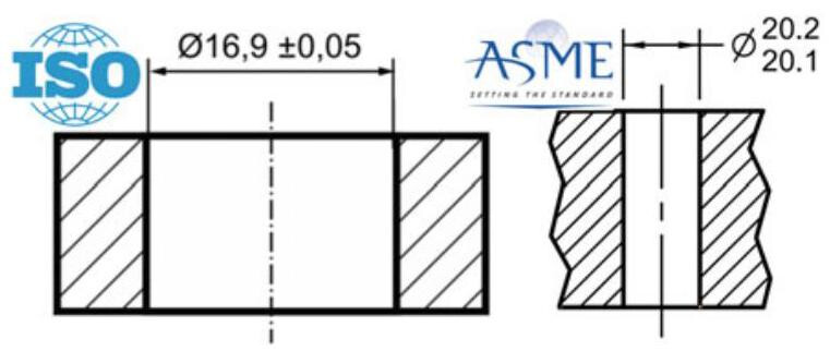
Fig. 4.30 A dot is utilised in the ASME standards as a decimal separation, while a comma is used in the ISO standards
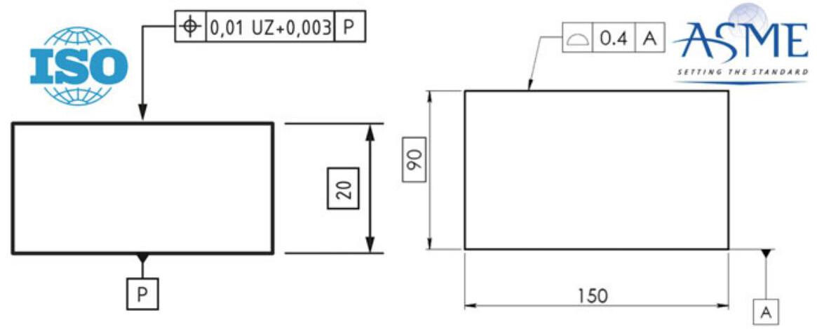
Fig. 4.31 The ASME standards specify that the symbol of location tolerance should only be utilised for features of size (that is, axes and median planes), while the ISO standards allow it to be used to locate surfaces
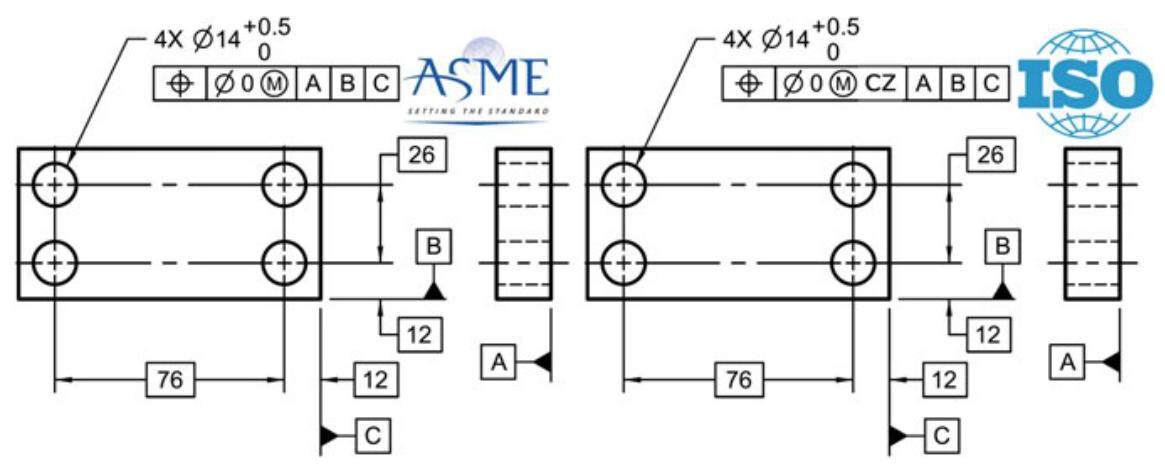
Fig. 4.32 In the ASME standard, the “4x” specification defines a tolerance zone pattern with orientation and position constraints. In ISO, the “4x” specification does not form a pattern. In order to create a tolerance zone pattern specification, it is necessary to use a CZ modifier
4.6.1 The Different Concepts of Pattern and Simultaneous Requirement
The ISO 5458:2018 standard establishes complementary rules to ISO 1101 for pattern specifications. According to the independency principle, a geometrical specification that applies to more than one single feature, by default also applies to those features independently. The tolerance zones defined by one tolerance indicator or by several tolerance indicators should by default be considered independently (this corresponds to the meaning of the modifier SZ, separate zone). In ISO, the 4 holes in Fig. 4.32 with the “4x” specification do not establish a pattern. In order to create a tolerance zone pattern specification, it is necessary to use a tolerance zone pattern modifier, such as CZ.
The use of the “Simultaneous requirement” concept transforms a set of more than one geometrical specification into a combined specification, i.e. a pattern specification.
In the ASME standard, a simultaneous requirement applies to position and profile tolerances that are located by means of basic dimensions related to common datum features referenced in the same order of precedence at the same boundary conditions. No translation or rotation takes place between the datum reference frames of the included geometric tolerances for a simultaneous requirement, thus a single pattern is created. If such an interrelationship is not required, a notation, such as SEP REQT, should be placed adjacent to each applicable feature in the control frame. Figure 4.33 shows an example of the simultaneous requirement principle applied to a two-hole pattern.
According to the ISO 5458:2018 standard, if the geometrical specification has to simultaneously apply to features with location and orientation constraints between the tolerance zones, it is necessary to use tolerance zone pattern modifiers, such as CZ, CZR or SIMn (Fig. 4.34).
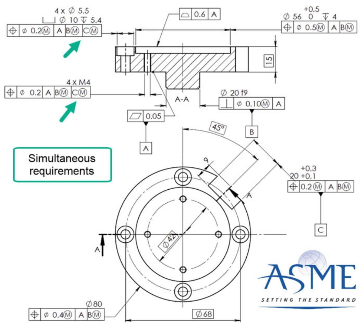
Fig. 4.33 The two pattern tolerance zones in the ASME drawing are simultaneously contained within tolerance zone frameworks related to the same Datum Reference Frame and are thus basically aligned
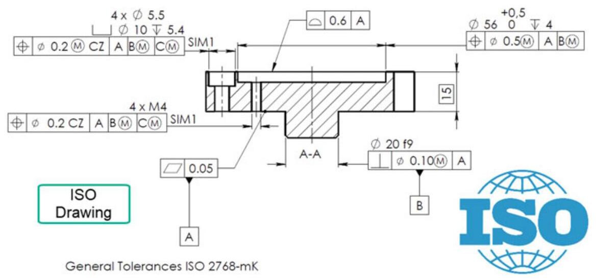
Fig. 4.34 In order to obtain the same functional requirements as the previous figure, the ISO standard uses CZ and SIM1 modifiers
Table 4.3 Comparison of ISO-ASME